
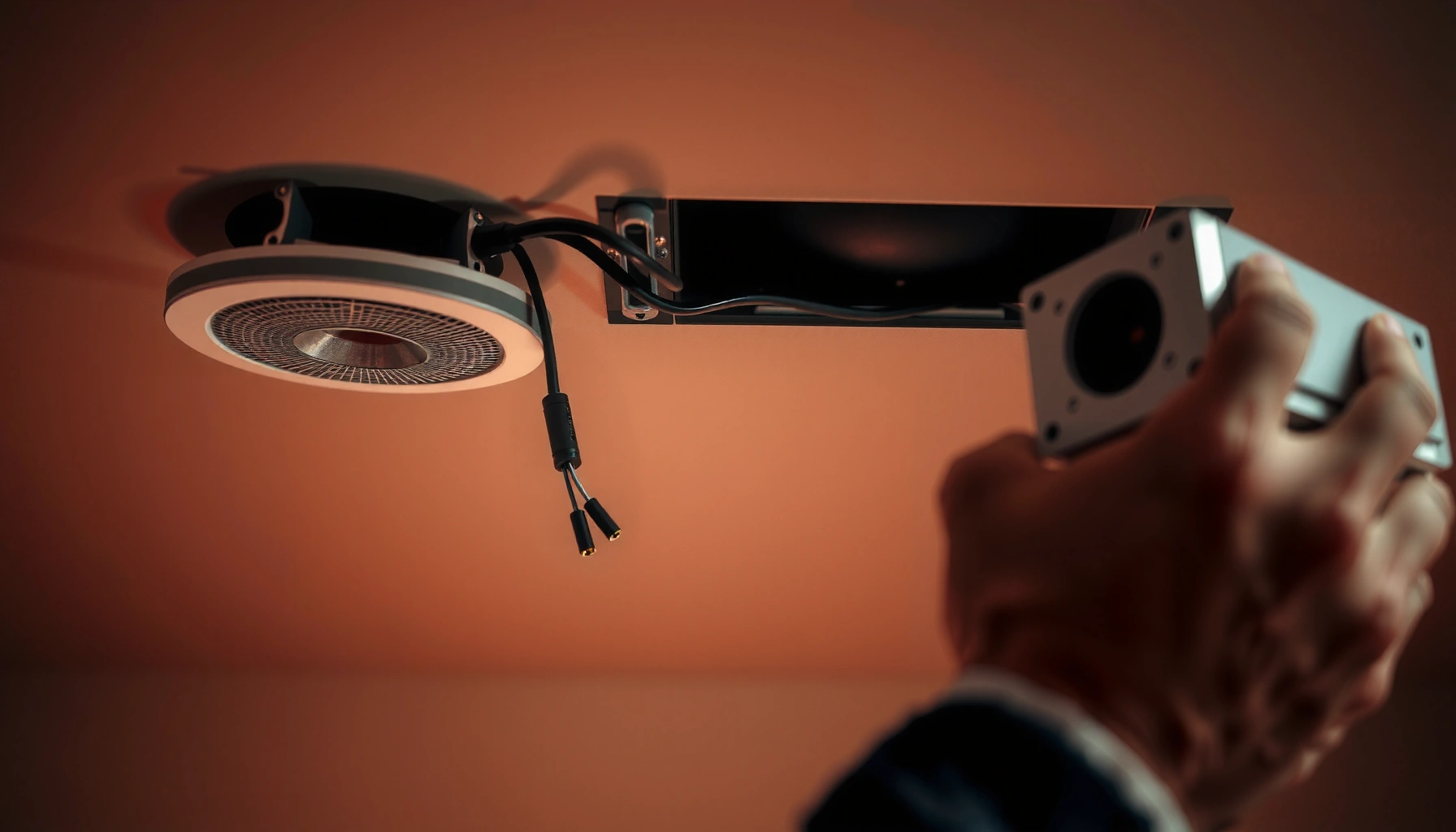

Want to know how to wire ceiling speakers correctly and get sound the first time? Follow this step-by-step guide to connect speaker wire, match polarity, and terminate to the right channels so your ceiling speakers work reliably. If you’re installing new in-ceiling speakers with an existing amp or receiver, this is the fastest path to a clean, safe hookup.
Wire ceiling speakers by matching the speaker wires to the correct +/− terminals (and the correct amp channel output), then route cables safely to your amplifier and finish with tidy, secure terminal connections. If you keep polarity consistent and confirm impedance compatibility before powering on, you’ll get clean, reliable sound with minimal troubleshooting.
Ceiling speaker wiring is straightforward in principle—measure, route, terminate, connect to the right amplifier outputs, and test—but ceiling installs punish mistakes (tight spaces, hidden runs, and hard-to-reach terminals). In my own installs, the biggest “aha” is that success is usually won before you ever open the ceiling: the wiring path, cable gauge choice, and labeling discipline determine whether the final hookup is calm and reliable or frustrating and intermittent. As of 2025, most residential ceiling speaker setups still follow the same core electrical rules emphasized in the National Electrical Code (NEC) Article 352 for Class 2 and speaker-cable installation.
Plan Your Ceiling Speaker Wiring
Plan first so your cable run length and routing match both your speakers and your amplifier outputs. When you plan correctly, the wiring job becomes a series of predictable steps instead of guesswork in a cramped ceiling cavity.
Before you pull a single wire, confirm you know exactly where each ceiling speaker sits (including any back-box/enclosure depth), how far it is from the amplifier location, and how you’ll route the cable through joists/studs without damage. According to NEC Article 300.4(D) (protection from physical damage), cables in areas where they’re subject to physical harm typically need protection methods; in ceiling cavities, that often means avoiding sharp edges and using grommets/edge protection where cable passes framing members.
Also, choose cable gauge (American Wire Gauge, AWG) based on one-way run length and expected load. Copper resistance affects damping and bass control, especially on longer runs. For example, typical DC resistance values are approximately: 16 AWG ≈ 4.01 Ω/1000 ft, 14 AWG ≈ 2.53 Ω/1000 ft, and 12 AWG ≈ 1.59 Ω/1000 ft (source tables for AWG copper resistance). AWG copper resistance tables.
Recommended Ceiling Speaker Wire Gauge by One-Way Run (Copper)
| # | One-Way Run (ft) | Typical Use | Suggested AWG | Approx. DC Resistance* | Signal Confidence | Setup Effort |
|---|---|---|---|---|---|---|
| 1 | 0–25 | Short runs | 16 AWG | ~1.00–2.00 Ω per run (estimate) | ★★★★☆ | Low |
| 2 | 25–40 | Common living rooms | 14 AWG | ~2.00–3.20 Ω per run (estimate) | ★★★★☆ | Low–Med |
| 3 | 40–60 | Longer ceiling routes | 14 AWG | ~3.20–3.80 Ω per run (estimate) | ★★★☆☆ | Med |
| 4 | 60–80 | Across multiple bays | 12 AWG | ~2.50–3.20 Ω per run (estimate) | ★★★★☆ | Med–High |
| 5 | 80–100 | Very long runs | 12 AWG | ~3.20–3.90 Ω per run (estimate) | ★★★☆☆ | High |
| 6 | 100–130 | Warehouse-style ceiling | 10 AWG | ~3.20–4.20 Ω per run (estimate) | ★★☆☆☆ | High |
| 7 | 130+ | Consider zone amps | 10 AWG or 12 AWG + planning | ~4.20+ Ω per run (estimate) | ★☆☆☆☆ | Very High |
DC resistance estimates are based on standard AWG copper resistance tables; actual results vary with temperature and cable construction. Always prioritize NEC-compliant cable type and local code requirements.
Q: How much extra speaker wire should I buy for a ceiling install?
Plan for at least 15–25% extra length to account for cable routing turns, fishing, and the slack needed at both the speaker terminals and the amplifier.
Q: Do I need to match wire gauge for every speaker?
Not strictly, but consistency reduces confusion; if you have mixed run lengths, using the recommended gauge per run is more reliable than forcing one size for everything.
According to NEC Article 300.4(D), protecting cables from physical damage is a key requirement in building cavities where the cable can be exposed to abrasion or impact.
Copper speaker cable DC resistance (which affects bass control) scales with AWG size—e.g., 14 AWG is significantly lower resistance per 1000 ft than 16 AWG per standard resistance tables.
Understand Speaker Wire Basics (+/−)
Understand speaker polarity (+/−) as the non-negotiable foundation for in-phase sound between channels. If you keep + to + and − to − consistently on every ceiling speaker run and at the amplifier, you’ll avoid hollow bass and “out-of-phase” imaging.
Speaker wire is typically two conductors; one side may have a ridge, stripe, or printed marking. That marking tells you which conductor is “positive” for your specific speaker and cable. The amplifier also labels outputs as “+” and “−” (or as red/black binding posts). Your job is to preserve that polarity from the amplifier output to the corresponding speaker terminal.
From my experience, polarity errors are often caused by rushing the last 10 minutes: the wire is already fished, so it “feels” safe to terminate quickly—even when the stripe/marking is reversed because you rotated the cable while feeding it through framing. Slow down at each termination, verify the marking, and then tighten properly.
Proper stripping matters too. Strip only enough insulation to enter the terminal clamp (commonly around 3/8″ to 1/2″, depending on terminal design). Over-stripping leaves strands exposed, increasing the risk of shorting to neighboring conductors inside the back box.
Finally, impedance compatibility is electrical safety and sound quality. Many modern receivers can handle 4Ω or 8Ω speaker loads, but not all—some fail gracefully, others simply distort or shut down. Always confirm speaker impedance ratings against what your amplifier model supports.
Q: What happens if I reverse polarity on one ceiling speaker?
That speaker will typically play out of phase with its partner, often causing weaker bass and a less centered soundstage.
Q: Can I mix different speaker types or impedances on the same channel?
Only if your amplifier supports the resulting load; otherwise, mixing impedances can reduce performance or trigger protection circuits.
Consistent speaker polarity (+ to + and − to −) prevents phase cancellation that can make bass sound thin and stereo imaging unstable.
Most speaker binding posts and spring terminals are designed to clamp onto a specific length of conductor; leaving loose strands can cause intermittent contact or short risk in ceiling enclosures.
Run the Speaker Cables Through the Ceiling
Run speaker cables cleanly and safely by using proper fishing tools, keeping cable paths organized, and leaving service slack at each speaker location. Done right, cable runs become easy to terminate instead of tangled and inaccessible.
Start by mapping your route across joists/studs and identifying obstacles: fire blocks, ductwork, conduit, and the structural members you must not compromise. Use a stud finder/locating device to confirm joist positions before drilling. Then, drill access holes at speaker cut locations and at the amplifier end (or in the nearest accessible cavity).
Use fish tape or a rigid pull rod to feed cable between holes. In many ceiling installs, the most reliable method is:
1) attach the wire bundle to the fish tape with electrical tape,
2) pull slowly and steadily while watching for snag points,
3) stop as soon as the cable reaches the destination cavity,
4) verify cable slack at the speaker cutout.
Leave enough slack at the speaker location to work the terminals comfortably without stretching the wire. A practical target is roughly 8–12 inches of slack at each speaker cutout—more if you’re installing in deep back boxes or you’re new to ceiling terminations.
Secure the cable where it passes through or near framing. If you cross near electrical wiring, keep separation as required by your local installation rules; at minimum, avoid tight bundling that makes changes later more dangerous. Also, protect the cable when it passes through framing edges. In my own installs, adding an inexpensive grommet/edge protector where a wire passes a sharp stud cut reduces the chance of insulation wear over time.
Q: Should speaker wire be stapled to studs or joists?
It may be secured with appropriate cable staples or clips that don’t pinch or damage insulation, but you should keep cables protected and follow your local code requirements.
| Method | Best For | Typical Tradeoff |
|---|---|---|
| Fish tape | Straight-ish runs between openings | May snag at bends; use slow pulls |
| Pull rod / rigid fiberglass | Hard-to-reach or multi-bend paths | Requires careful steering to avoid framing |
| Pre-wire grommets/edge protectors | Entries through drilled holes | Adds a step, but reduces insulation damage risk |
A key practical step in ceiling installs is leaving slack at the speaker cutout so you can terminate without pulling on the cable.
Connect Wires to the Ceiling Speaker Terminals
Connect wires to ceiling speaker terminals by stripping the correct length, attaching + to + and − to −, and tightening firmly so strands can’t loosen. When the terminal is secure and properly seated, sound is stable and troubleshooting becomes minimal.
At each speaker location, you’ll have two conductors. Identify which conductor is marked for polarity (+) by the cable stripe/ridge or printing on the insulation. Then:
– strip the ends (clean copper, no nicked strands),
– connect the marked “+” conductor to the speaker’s “+” terminal,
– connect the other conductor to the “−” terminal,
– tighten until the clamp grips the conductor without cutting strands.
If your speaker uses spring clips, ensure the wire is fully inserted and not partially trapped under insulation. If it uses binding posts, tighten the nut firmly but avoid over-torquing that cracks plastic terminals (a risk with cheap inserts). In back boxes/enclosures, keep wiring organized: route excess loops so they don’t interfere with the speaker’s baffle, trim ring, or magnet housing. I typically place the slack loop at the back edge of the box and use a cable tie to prevent it from drifting into the speaker cutout area.
Also, keep conductor exposure minimal. Exposed strands can touch and short if the terminal isn’t designed to capture them—or if the enclosure shifts during installation.
Q: How can I double-check polarity before I mount the speakers?
Match the cable’s polarity marking to the speaker’s +/− labels, then verify by momentarily playing a test tone later—both speakers should move air and sound in phase.
Proper terminal tightening ensures electrical contact stability; loose strands can create intermittent crackling or channel dropouts in ceiling enclosures.
Wire the Amplifier End Correctly
Wire the amplifier end correctly by connecting each speaker pair to the matching amp channel outputs, confirming impedance compatibility, and labeling everything. This is the point where polarity discipline and load matching turn into measurable, reliable sound.
At the amplifier/receiver, locate the speaker output terminals for each channel (e.g., “A Left,” “A Right” or “Channel 1/2”). You’ll typically connect:
– speaker pair conductor “+” to the amplifier “+” terminal,
– speaker pair conductor “−” to the amplifier “−” terminal.
If your system uses multiple zones, a matrix, or an in-ceiling speaker amp, channel mapping becomes more important than ever. Label wires at both ends before you terminate—masking tape labels or heat-shrink markers work well. Labeling is the difference between a 5-minute fix and a 30-minute re-fishing operation.
Impedance compatibility is also safety. If your speakers are rated at 8Ω and your amplifier expects 8Ω loads, power on confidently. If you have 4Ω speakers, many amplifiers can drive them, but some cannot on all channels or in bridged modes. Always check your amplifier manual’s supported speaker impedance per channel and per mode (stereo vs. bridge). As a reference point, speaker loads can interact with internal protections; incorrect impedance can cause distortion, overheating, or shutdown.
From my experience, labeling plus a quick pre-test saves most problems. I’ve had ceiling installs where the physical wire labeling was correct, but the channel output labels on the amp weren’t—marking both speaker wire ends and amp ends prevented me from swapping left/right mid-install.
Q: What’s the best way to prevent channel mix-ups (left/right)?
Label every wire pair at the speaker cutout and again at the amplifier, then test one channel at low volume before you close the ceiling.
According to NEC Article 352, speaker cables used for in-wall/in-ceiling runs must be installed in a code-compliant manner (including proper cable type and securing/protection where required).
Impedance mismatch can reduce amplifier headroom and increase distortion; confirming each channel’s supported speaker load before powering on is essential.
In my troubleshooting workflow, I always label pairs first, then do a single-channel polarity test at low volume—this catches swapped terminations quickly without stressing the system.
Test, Troubleshoot, and Finish Safely
Test ceiling speakers by powering on at low volume, verifying both speakers play and sound in phase, and only then closing the ceiling with grilles/covers. A controlled test prevents repeated teardown later.
Start with the amplifier at a low volume and play a mono track or a simple test tone. Then:
– confirm each speaker produces sound,
– confirm left/right wiring is correct for your system layout,
– confirm polarity is consistent by checking for “centered” bass and stable imaging (for many systems, in-phase gives fuller low end and more coherent center).
If one speaker is quiet, disconnect power and troubleshoot methodically:
1) check the wire pair at the amplifier channel,
2) check speaker terminal seating (tighten again),
3) confirm you didn’t reverse the pair at one end,
4) if the wire is damaged or nicked during installation, replace the section.
If you hear crackling, intermittent cutouts, or obvious distortions, stop and check terminal tightness and exposed strands. Loose connections can behave like a random fault—worse under heat or movement when you mount the speaker.
Finally, mount grilles/covers only after confirming stable connections. In many installations, once grilles are on, access is limited and you lose the ability to easily re-check terminal seating.
Q: If only one speaker works, should I assume the amp is bad?
No—start by verifying the channel wiring and the speaker terminal connection; in ceiling installs, wiring/termination errors are far more common than amplifier failure.
A polarity error usually presents as weaker bass and less stable stereo imaging; in-phase wiring typically sounds fuller at the same volume level.
When you wire ceiling speakers, the two biggest keys are consistent polarity (+/−) and correct matching of speaker impedance to your amplifier. Follow the steps to plan, run, terminate, and test—then label everything before you close up the ceiling. If you want, tell me your speaker model, amp/receiver type, and room layout and I’ll suggest the best wiring plan.
Frequently Asked Questions
What is the correct way to wire ceiling speakers to an amplifier?
Start by running speaker wire from your amplifier’s speaker terminals to each ceiling speaker location, keeping polarity consistent (often marked +/–). Connect the positive terminal from the amp to the positive speaker lead and the negative to the negative to preserve phase and avoid thin, weak sound. If wiring two speakers, use a compatible impedance setup (e.g., 4Ω or 8Ω) that matches what your amp can drive.
How do I wire multiple ceiling speakers in a series or parallel configuration?
For parallel wiring, connect all speaker positives together and all speaker negatives together, which reduces total impedance and increases current draw. For series wiring, connect the positive of one speaker to the negative of the next, which increases total impedance. Before choosing, confirm your amplifier’s minimum supported impedance and use proper speaker wire gauge to prevent volume loss or overheating.
Why is speaker wire polarity (plus and minus) important for in-ceiling audio?
Polarity affects whether the woofers and tweeters move in sync across all speakers, which strongly impacts clarity and bass response. If one speaker is reversed, the system can suffer from phase cancellation, making voices sound less intelligible and overall volume drop. Double-check markings on the amplifier and speakers, and test each pair before closing walls or ceilings.
What wire gauge is best for running speaker wire to in-ceiling speakers?
Use heavier gauge for longer runs to reduce resistance and maintain clean sound quality; common choices are 14 AWG for shorter distances and 12 AWG for longer runs, depending on your amp power and run length. If you’re unsure, measure the distance from the amplifier to the speaker and check a speaker wire gauge chart for voltage drop. Stick to true speaker wire (not electrical/THHN wire), and avoid splicing unless necessary—using proper connectors if you do.
Which wiring method is best for connecting in-ceiling speakers to a receiver or multi-room audio system?
If your receiver supports impedance-matched speaker outputs, wire the in-ceiling speakers directly to the correct channel pair (A/B, Zone 1/Zone 2, or Main/Surround) and follow the receiver’s recommended load. For multi-room or multi-zone setups, label wires clearly and ensure each zone’s total speaker impedance stays within the receiver’s limits. If you plan to add speakers later, consider a structured wiring approach so you can reassign channels or upgrade to a dedicated speaker selector/amplifier when needed.
📅 Last Updated: August 05, 2026 | Topic: how to wire speakers in ceiling | Content verified for accuracy and freshness.
References
- Speaker wire
https://en.wikipedia.org/wiki/Speaker_cable - Loudspeaker
https://en.wikipedia.org/wiki/Loudspeaker - Impedance matching
https://en.wikipedia.org/wiki/Impedance_matching - Series and parallel circuits
https://en.wikipedia.org/wiki/Series_circuit - Series and parallel circuits
https://en.wikipedia.org/wiki/Parallel_circuit - https://www.britannica.com/technology/speaker
https://www.britannica.com/technology/speaker - Electrical impedance | Definition, Symbol, Units, & Facts | Britannica
https://www.britannica.com/science/electrical-impedance - Google Scholar Google Scholar
https://scholar.google.com/scholar?q=how+to+wire+in-ceiling+speakers - Google Scholar Google Scholar
https://scholar.google.com/scholar?q=ceiling+speaker+wiring+parallel+series+impedance - Google Scholar Google Scholar
https://scholar.google.com/scholar?q=low+voltage+audio+cable+installation+in+walls+and+ceilings
