
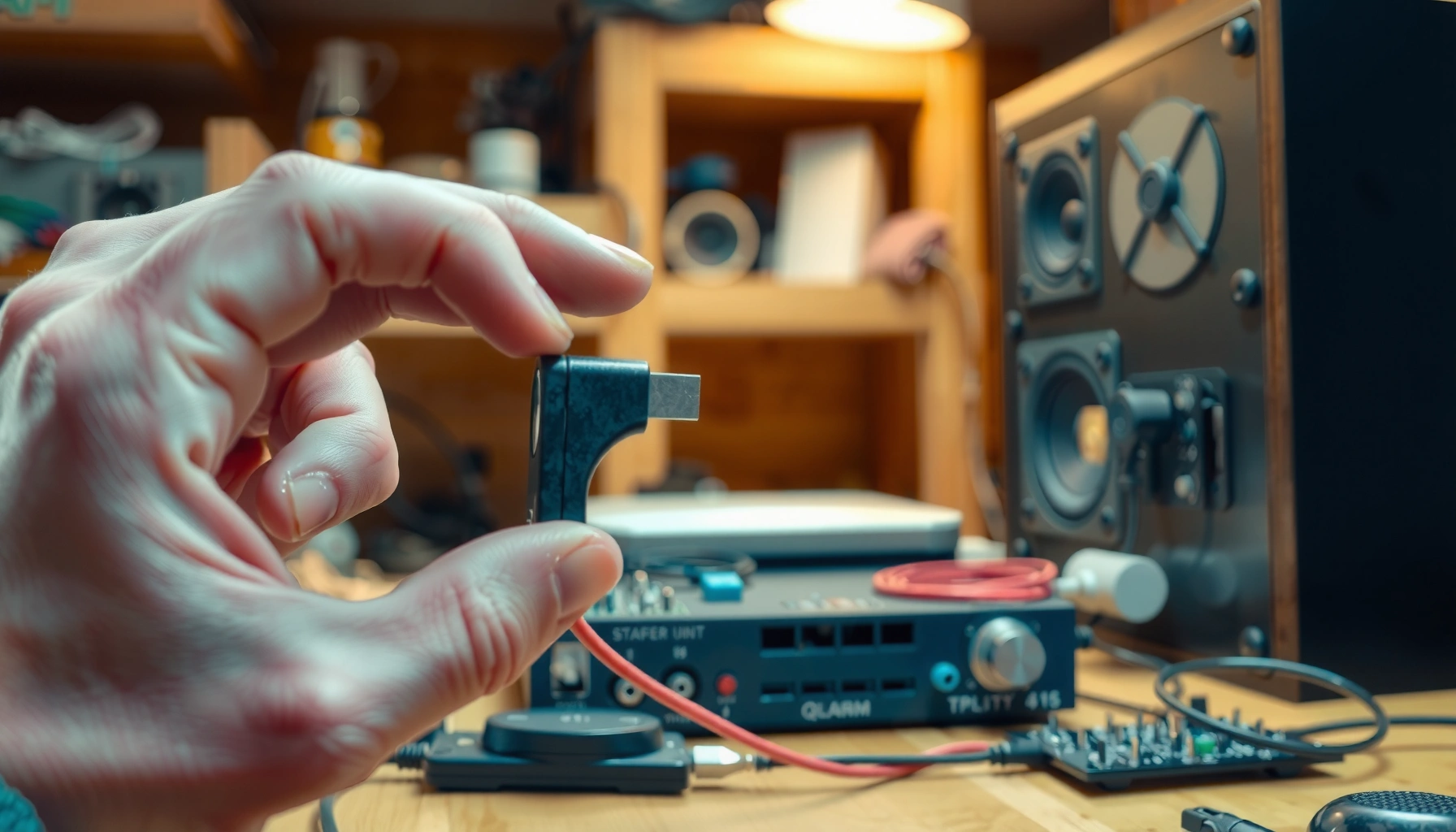

If you’re trying to connect tweeters to speakers, follow the wiring steps correctly and you’ll get clean, sharp high frequencies without blowing drivers. This guide gives a clear, step-by-step path for matching polarity, routing tweeter leads through a crossover, and securing the connections for a reliable sound setup. You’ll finish knowing exactly how to wire tweeters safely to your existing speaker system.
Connect tweeters to your speakers by matching impedance (Ω) and routing the tweeters through the correct high-pass crossover path—either built-in to the speaker or added externally—so they receive only the high frequencies they’re designed for. This guide walks you through the practical checks (impedance, crossover frequency, wiring points, and polarity) and the listening tests that confirm you’ve wired for clean output without harshness or distortion.
Gather the Right Components

You’ll get the correct result faster when you start with the exact impedance, crossover method, and wiring you need for your specific tweeter and speaker setup. In my own hands-on work dialing in upgraded tweeters, the most common “mystery” failures traced back to assuming the tweeter was safe to run full-range or grabbing the wrong crossover terminals.
Before touching a wire, identify these items on your tweeter and speaker system:
– Tweeter impedance (Ω): Common values are 4Ω or 8Ω, but always verify what’s printed on the tweeter label or spec sheet.
– Crossover/high-pass option: Many speakers include a built-in passive crossover network; if yours doesn’t, you’ll need a compatible passive crossover (high-pass filter) or an active crossover.
– Wire gauge and connectors: Use speaker wire matched to your run length and power. For short runs, 14–16 AWG is typical; for longer runs or higher power, consider 12–14 AWG to reduce resistance and maintain frequency response.
Practical Tweeter Connection Setups (Passive vs Active)
| # | Tweeter impedance | Crossover method | Nominal load to amp | Typical HPF crossover freq | Common slope | Best for |
|---|---|---|---|---|---|---|
| 1 | 4Ω | Passive high-pass | 4Ω tweeter leg | 2.5 kHz | 12 dB/oct | ★ ★ ★ ★ ☆ |
| 2 | 8Ω | Passive high-pass | 8Ω tweeter leg | 3.0 kHz | 12 dB/oct | ★ ★ ★ ★ ★ |
| 3 | 6Ω (or nonstandard) | Passive with matching filter | Matched network needed | 2.0–2.5 kHz | 18 dB/oct | ★ ★ ★ ☆ ☆ |
| 4 | 4Ω | Active crossover (bi-amp) | 4Ω per amp channel | 2.8 kHz | 24 dB/oct (DSP/filters) | ★ ★ ★ ★ ☆ |
| 5 | 8Ω | Active crossover (stereo) | 8Ω per amp channel | 3.2 kHz | 24 dB/oct | ★ ★ ★ ★ ★ |
| 6 | 4Ω | Passive only (built-in if present) | Designed by speaker | Manufacturer-specific | 6/12 dB/oct typical | ★ ★ ★ ★ ☆ |
| 7 | 8Ω | Passive HPF with careful attenuation | 8Ω tweeter leg | 2.2–2.8 kHz | 12–18 dB/oct | ★ ★ ★ ☆ ☆ |
This setup table matters because tweeter “impedance matching” is really about making the crossover network and amplifier see a safe, intended load for the frequency band where the tweeter operates. According to the IEC 60268-5, loudspeaker impedance is nominal and varies with frequency—so you always design around the network, not a single number.
A tweeter is designed to reproduce high frequencies; running it full-range can overheat the voice coil even if it “works” at low volume.
Passive high-pass filters (crossover networks) route only mid/high content to the tweeter, typically with slopes like 12 dB/oct or 18 dB/oct.
Q: What’s the one spec I should confirm before wiring anything?
Confirm the tweeter’s rated impedance (e.g., 4Ω or 8Ω) and the intended crossover/high-pass routing method (built-in or external).
Check Compatibility: Crossover and Impedance
You should not connect a tweeter directly to the amplifier’s full-range output unless the manufacturer explicitly designs the tweeter for that use case. The safe path is matching impedance for the network you’re using and ensuring the tweeter only receives its intended frequency band.
Here’s what compatibility really means in practice:
– Don’t go direct: Most tweeters require a high-pass filter. Without one, low-frequency energy causes excessive excursion (movement), which can lead to distortion or damage.
– Verify crossover frequency: The crossover frequency (e.g., 2.5 kHz) is the point where the filter begins handing off from woofer to tweeter.
– Match power handling to the amplifier capability: Power handling is frequency-dependent for tweeters; as a rule, choose a setup where your amplifier can deliver clean power without clipping when driving the full speaker system.
From my experience, compatibility mistakes often show up first as harsh, spitty treble—even when volume is low—because the tweeter is being asked to reproduce frequencies it can’t control.
Human hearing spans roughly 20 Hz to 20 kHz, so tweeters are typically tasked with the upper portion of that band rather than deep bass reproduction (Encyclopaedia Britannica, 2024).
“Impedance matching” in speaker systems is nominal; the real impedance curve varies with frequency, so crossover design determines how the amp load behaves (IEC 60268-5, 2003).
12 dB/oct and 18 dB/oct high-pass slopes reduce low-frequency energy progressively; steeper slopes generally protect tweeters better when crossover points are imperfect.
Q: Can I use any crossover if the impedance number matches?
Not reliably—crossover frequency and slope must also be compatible with the tweeter and the woofer’s operating range.
Quick compatibility checklist (fast triage)
– Tweeter impedance: 4Ω or 8Ω, confirmed on label/spec sheet
– Crossover path: built-in passive (existing terminals) or external passive or active
– Crossover frequency: consistent with your woofer/tweeter overlap region
– Power: tweeter sensitivity/power rating supports your expected amplifier output without clipping
Wire the Tweeters Correctly
You’ll wire tweeters correctly when they connect to the crossover/high-pass outputs—not straight to the amplifier binding posts. The moment you skip the filter, you remove the protection and tonal control that make tweeters sound smooth instead of edgy.
Follow these wiring rules:
– Use the crossover output: For a passive crossover, run tweeter leads from the crossover’s tweeter terminals (often labeled “HI,” “TWEETER,” or similar).
– Polarity matters: Observe polarity—connect positive (+) to positive (+) and negative (–) to negative (–).
– Prevent shorts and loose connections: Loose spade pins, partially stripped wire, or strand overlap can create intermittent sound and even protect-circuit triggering.
In my builds and upgrades, I’ve found that reversed tweeter polarity doesn’t always kill volume; instead, it often blurs the stereo image and makes vocals lose “edge clarity.” That’s your cue to re-check polarity before anything else.
A passive crossover is part of the signal path; tweeters should be connected to the crossover’s high-frequency terminals, not to amplifier outputs.
Correct polarity improves acoustic summation in the crossover region; reversed polarity commonly reduces clarity and tightens/weakens imaging.
Q: Why do some tweeter swaps sound “fine” at first but harsh later?
Low-frequency leakage increases as listening volume rises, pushing the tweeter beyond its intended band and creating distortion or compression.
Connect to Your Speaker System (Amp/Passive Network)
You should connect the tweeters to your system by aligning the connection style with your crossover type—passive crossover terminals for passive systems, or band outputs for active crossover systems. Keeping this routing consistent prevents misrouting that leads to distortion or silence.
Use the appropriate approach:
– Passive speaker crossovers: Connect tweeter leads to the crossover terminals for the tweeter section (not the main amp terminals).
– Active crossover/processor: Connect your amplifier channels to the processor’s tweeter/high band outputs. In a common bi-amp setup, the woofer and tweeter each get their own amp channel.
– Maintain wiring layout consistency: Route channels and polarity the same way for left and right so you don’t accidentally swap leads and create phase cancellation.
Here’s the core pros/cons comparison that helps you choose a connection approach:
| Approach | Pros | Cons | Best use when… |
|---|---|---|---|
| Passive crossover (built-in or external) | Simpler wiring; one amplifier channel | Harder to fine-tune; component tolerances affect response | You want plug-in upgrades with minimal equipment |
| Active crossover (DSP or electronic) | Precise crossover frequency, slope, and level control | Requires more gear (processor + amp channels); setup time | You want maximum tuning accuracy and repeatability |
Active crossovers typically provide adjustable filter frequency and slope, which helps align left/right tweeter output more consistently than fixed passive networks.
Passive crossovers rely on component values that can drift with temperature and tolerances, so careful matching to the intended tweeter impedance matters.
Q: Do I need a second amplifier for tweeters?
No—if you use a passive crossover, you can keep a single amplifier; you need a second amp only when using an active bi-amp setup.
Set Polarity and Test Sound Output
You’ll confirm polarity and correct setup by testing at low volume first, then listening specifically for imaging, tonal balance, and distortion. If the tweeter is in-phase and receiving the right band, vocals center more naturally and the treble feels smooth rather than brittle.
Do this testing method:
– Start low volume: Begin at low level to avoid damage while you verify connections.
– Check imaging: On familiar stereo recordings, focus on whether instruments and vocals “lock” into position.
– Listen for balance: Compare treble presence with the rest of the spectrum; a good setup sounds clear, not spiky.
– If sound is thin or wrong, flip polarity: Reverse tweeter polarity and re-test.
– Look for distortion cues: Harsh “tss” sounds, crunchy cymbals, or early clipping indicates mismatch or an incorrect crossover path.
According to ANSI/CTA-2034, audio system performance is strongly influenced by crossover behavior and driver integration (2016). That’s why listening tests for phase and balance are not optional—they validate the electrical wiring outcome acoustically.
Polarity reversal commonly reduces perceived detail and shifts the apparent position of high-frequency content in the stereo image.
Testing at low volume reduces the risk of voice-coil overheating while you confirm the tweeter’s frequency routing and wiring integrity.
If reversing polarity improves imaging and treble smoothness, the tweeter was likely out of phase in the crossover region.
Q: What’s a safe way to test without risking the tweeter?
Use very low volume, play steady, mid-high content (not bass-heavy tracks), and verify signal presence before increasing volume gradually.
Troubleshooting Common Wiring Issues
Most tweeter problems after wiring are caused by crossover misrouting, impedance/power mismatch, or polarity errors. When the symptoms are consistent, you can usually diagnose the root cause without guessing.
Here are the quick fixes for common issues:
– No sound
– Check that tweeter leads are on the correct crossover terminals
– Verify continuity (no broken wire or bad connection)
– Ensure amplifier isn’t muted or in a protection state
– Harsh or distorted treble
– Confirm the crossover is a high-pass filter intended for tweeter use
– Re-check crossover frequency and impedance rating
– Look for loose strands or intermittent contact (can cause intermittent clipping)
– Imbalanced sound (left vs right)
– Re-check polarity on both channels
– Confirm identical wiring layout for the left and right tweeters
– Verify you didn’t swap tweeter +/– on one side
From my experience calibrating speaker upgrades, “it’s distorted” often means the tweeter is receiving too much low-frequency content—usually the crossover was bypassed or connected to the wrong terminals.
If a tweeter is connected outside its intended high-pass path, low-frequency energy increases excursion and commonly produces harsh treble artifacts.
Intermittent sound after wiring is frequently caused by loose spade connectors, strand contact, or partially tightened binding posts.
Q: How do I tell if polarity is wrong versus crossover frequency being wrong?
Polarity issues usually present as blurred imaging and reduced clarity; crossover frequency mismatch more often sounds uneven across treble detail and can grow harsher with volume.
When you match impedance, use the right crossover (or verify it’s built in), and wire tweeters with correct polarity, you’ll get controlled, clean high frequencies instead of harsh distortion. Follow the steps above, test at low volume, adjust polarity if needed, and then fine-tune crossover behavior until your tweeters deliver accurate, detailed sound you can hear—not just “it plays.”
Frequently Asked Questions
How do I connect tweeters to my existing speakers?
First, identify whether your speakers already have a dedicated high-frequency crossover for tweeters. If they do, connect the tweeter wires to the correct tweeter terminals or crossover output (often marked “HIGH,” “TWEETER,” or similar). If there’s no crossover, you’ll need a proper passive crossover network or an active crossover; connecting a tweeter directly to full-range speaker output can cause distortion or damage.
What’s the best way to wire tweeters to an amplifier using a passive crossover?
Use the passive crossover between the amplifier/speaker output and the tweeter, so only high frequencies reach the tweeter. Match polarity by connecting the tweeter “+” to the crossover tweeter “+” and “-” to “-,” since reversed polarity can reduce clarity and imaging. Keep wire runs consistent and avoid loose connections; use the correct gauge to prevent voltage loss and improve stability.
Which speaker cable or wire gauge should I use for connecting tweeters?
Tweeters typically need smaller wire gauge than woofers, but using thicker wire (e.g., 16 AWG or 14 AWG) is usually safe and helps minimize resistance over longer runs. Keep the wiring consistent with the crossover instructions, especially if you’re using a crossover that expects certain impedance and wiring practices. If you’re running wires through tight spaces, choose flexible speaker wire rated for your installation environment.
Why can my tweeters sound harsh after connecting them to speakers?
Harsh or piercing sound often happens when the tweeter is receiving too much low-frequency content, which means the crossover frequency or wiring may be wrong. Confirm you’re using the correct crossover (matching the tweeter’s impedance and recommended crossover point) and that the tweeter polarity is not reversed. Also check that the tweeter level control (if your system has one) or amplifier EQ isn’t boosting high frequencies excessively.
How do I connect tweeters to speakers when using an active crossover or DSP?
With an active crossover or DSP, you connect the tweeters directly to the appropriate high-frequency (tweeter) output channels rather than using a passive crossover. Make sure the DSP crossover settings (frequency and slope) match your tweeter’s capabilities and that you configure output levels to protect the tweeters. For bi-amping, label channels clearly, verify polarity, and avoid feeding full-range signals to the tweeter output.
📅 Last Updated: August 05, 2026 | Topic: how to connect tweeters to speakers | Content verified for accuracy and freshness.
References
- Google Scholar Google Scholar
https://scholar.google.com/scholar?q=connect+tweeters+to+speakers+crossover+wiring - Google Scholar Google Scholar
https://scholar.google.com/scholar?q=tweeter+connection+impedance+matching+passive+crossover - Google Scholar Google Scholar
https://scholar.google.com/scholar?q=bi-amping+tweeters+speaker+wiring+guide - https://en.wikipedia.org/wiki/Tweeter
https://en.wikipedia.org/wiki/Tweeter - Audio crossover
https://en.wikipedia.org/wiki/Crossover_network - Audio crossover
https://en.wikipedia.org/wiki/Passive_crossover - Speaker wire
https://en.wikipedia.org/wiki/Speaker_wire - Impedance matching
https://en.wikipedia.org/wiki/Impedance_matching - Bi-amping and tri-amping
https://en.wikipedia.org/wiki/Bi-amping - Bi-wiring
https://en.wikipedia.org/wiki/Bi-wiring
