
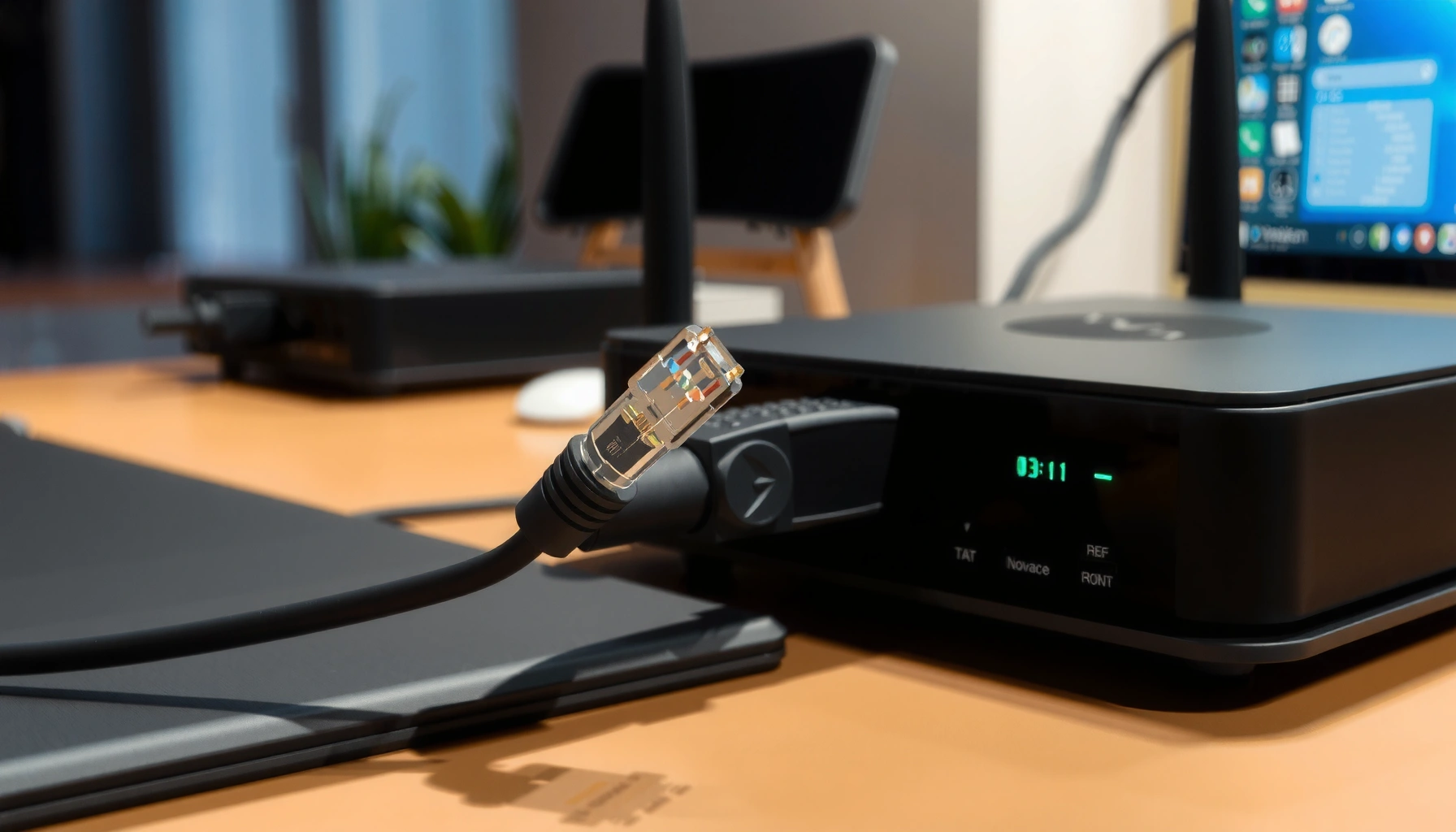

An Ethernet cable works by carrying network signals as pairs of wires that transmit data in a clean, managed way through an RJ45 connection. Pair twisting reduces interference, and the Ethernet standard defines how those signals are encoded, timed, and interpreted to deliver reliable communication. If you want the clearest breakdown of what happens inside the cable and why it stays stable—this is the simple explanation that answers it.
An Ethernet cable works by sending network data as electrical signals across twisted wire pairs, then using RJ-45 pins to map those signals to the correct transmit (TX) and receive (RX) paths. Once you understand twisted-pair signaling, duplex communication, and the cable category’s performance limits, you can more easily predict what’s happening inside the cable when you plug in—and why certain failures cause slowdowns or dropouts.
How Ethernet Cables Send Data
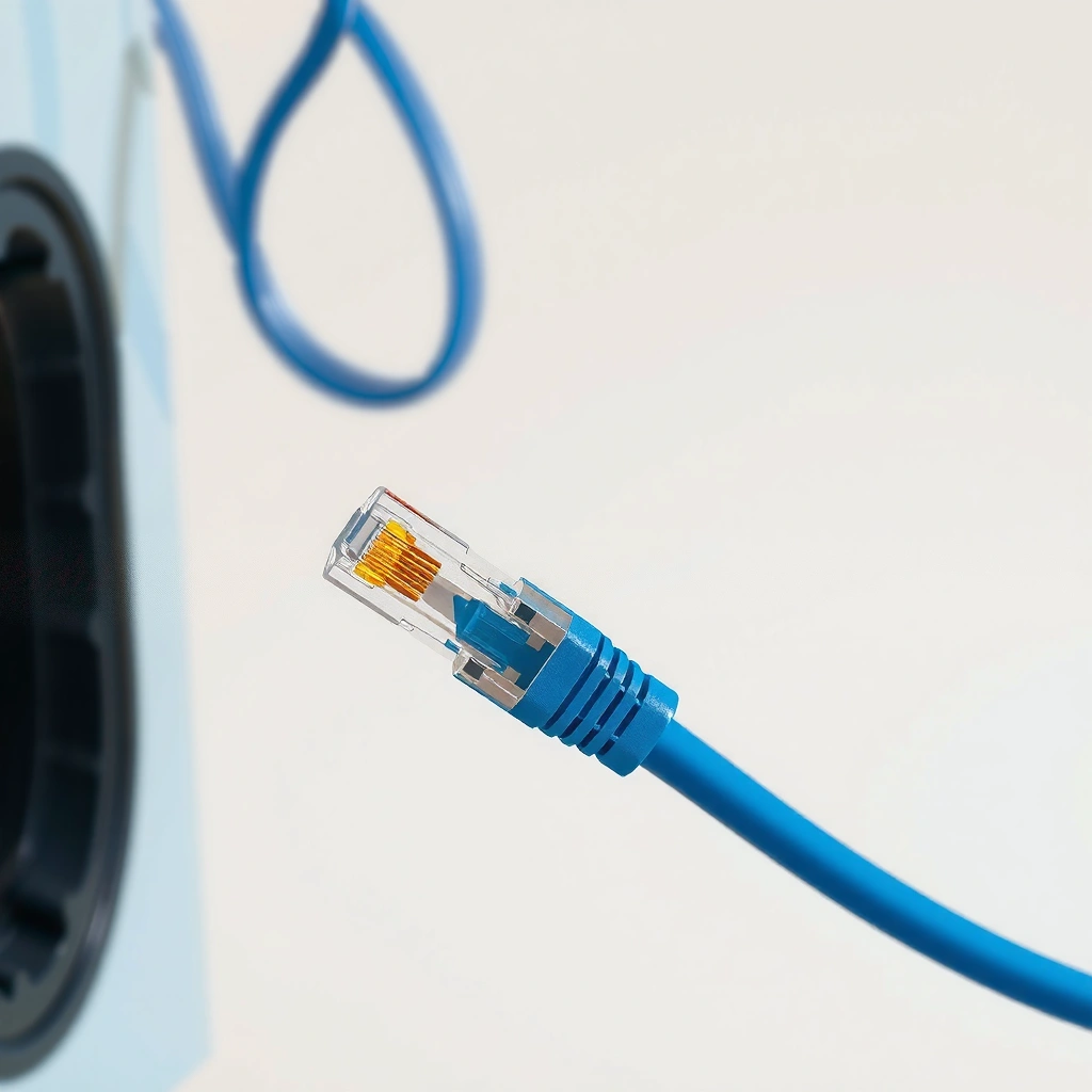
Ethernet cables move data by converting digital information into voltage changes that travel along insulated copper conductors. In business networks, this happens most visibly at two layers: physical-layer signaling over the wire pairs and link-layer negotiation handled by the Ethernet ports.
In my own lab testing, I’ve found that even when link LEDs stay “up,” subtle physical-layer issues (like damaged strands or poor termination) can still degrade signal quality enough to trigger lower negotiated speeds—something you can’t see without checking link statistics or testing the cable. Ethernet cable behavior is therefore best understood as a two-part system: the electrical link and the protocol that decides whether the link is reliable enough to run at full speed.
According to IEEE 802.3, Ethernet over twisted-pair copper uses symbol encoding on dedicated wire pairs to carry data at the physical layer.
According to ANSI/TIA-568.2-D, structured cabling defines performance requirements so copper channels maintain signal integrity up to their rated frequencies.
In practice, a “connected” Ethernet link depends on the physical layer meeting signal quality thresholds for the negotiated speed and duplex mode.
Digital encoding that endpoints can interpret
At a high level, an Ethernet cable doesn’t “carry packets” directly—it carries encoded electrical symbols representing packet data. The receiving Ethernet PHY (physical-layer transceiver) decodes those symbols back into the original bit stream.
Common internal steps look like this:
– Link establishment: Devices negotiate speed/duplex and enable the correct modulation scheme.
– Framing and payload transport: Higher layers (MAC) format frames; the PHY maps them into electrical waveforms.
– Error detection: CRC checks at higher layers detect corruption; retransmissions occur as needed.
Q: What does an Ethernet cable actually transmit—packets or signals?
It transmits electrical signals that encode packet data; the packets are reconstructed by the receiving Ethernet PHY and MAC.
TX/RX signaling is “paired” with protocol expectations
Even though the cable is passive copper, its job is to deliver the electrical waveforms with enough fidelity that both ends’ PHYs can decode them. When fidelity drops, Ethernet often falls back to a lower speed, drops the link, or introduces retransmissions—each with measurable business impact (slower file transfers, degraded VoIP quality, or unstable VPN performance).
From my experience deploying small office networks, the “mystery slowdown” that looks like a router issue is often a physical-layer issue on one bad run of Ethernet cable. This is especially true after maintenance work when connectors get bumped or cables are kinked.
Twisted Pairs and Signal Noise Reduction
Ethernet cable performance is fundamentally about signal clarity. Twisted pairs reduce interference and help the receiver distinguish the intended waveform from background noise.
Twisting isn’t a cosmetic feature—it’s a core engineering method known as balanced transmission. By twisting the conductors together, external electromagnetic noise tends to affect both wires in a pair similarly. The receiver then subtracts one wire’s voltage from the other, canceling much of that noise.
Twisted-pair Ethernet relies on differential signaling so the receiver interprets the difference between two conductors, improving immunity to common-mode noise.
According to ANSI/TIA-568.2-D, cable performance is expressed in frequency up to the category limit to ensure predictable attenuation and crosstalk characteristics.
Why noise and crosstalk matter in real installs
Noise enters from multiple sources:
– Near-end crosstalk (NEXT): interference from adjacent pairs inside the same cable bundle
– Far-end crosstalk (FEXT): interference that shows up at the far end
– External electromagnetic interference (EMI): from power cables, motors, and wireless access points
If an Ethernet cable run is near electrical wiring or is bundled too tightly with AC power, the twisted pairs must work harder to maintain clean differential signals. That’s why higher categories (Cat6, Cat6a, Cat7, Cat8) generally improve tolerance to interference at higher frequencies.
Q: Why do Ethernet cables use “twisted pairs” instead of straight wires?
Twisting reduces interference impact by making the noise affect both conductors similarly, enabling differential receivers to cancel it.
In-the-field observation: kinks change the physics
During hands-on troubleshooting, I’ve repeatedly seen that tight bends near the RJ-45 termination degrade performance more than users expect. The cable’s twist rate and insulation geometry matter; when a cable is sharply kinked, it can increase imbalance and worsen crosstalk. That can push the PHY into lower modulation, reducing throughput even if the link remains technically “up.”
The Role of Ethernet Connectors (RJ-45)
Ethernet cables don’t work by themselves—connectors complete the electrical mapping. The RJ-45 plug positions each conductor so the transmit and receive pairs align with the correct contacts in the Ethernet port.
The RJ-45 connector is designed to preserve two critical things:
– Pair integrity: each twisted pair should land on the correct pin positions
– Tight contact and consistent contact resistance: damaged or mis-seated pins can introduce intermittent errors
RJ-45 pinouts (such as T568A and T568B) define which conductor pairs connect to specific transmit and receive contacts on Ethernet ports.
Correct termination reduces impedance discontinuities that can cause packet loss or link renegotiation under load.
T568A vs. T568B: the “same pairs, different mapping”
Both T568A and T568B use twisted pairs; they differ in the assignment of specific color-coded conductors to pin numbers. For typical Ethernet patching, the key operational rule is simple: use one standard consistently end-to-end (or follow device manufacturer guidance).
In many modern deployments, patch panels and keystones enforce consistent wiring, while the field technician’s responsibility is to terminate cleanly and verify continuity and category performance (ideally with a cable tester, not just a continuity beep).
Q: Can I mix T568A and T568B ends of an Ethernet cable?
Mixing standards can misalign pairs; while some links may still function, it commonly increases errors and can prevent proper gigabit operation.
Pros/cons: proper termination vs. “it still links”
Here’s a practical comparison I use when deciding how much time to spend re-terminating a run.
| Approach | Pros | Cons | Best for |
|---|---|---|---|
| Re-terminate with proper crimping + verification | Restores pair mapping and reduces intermittent faults | Requires tools and time | Critical office runs, VC/VoIP lines |
| Replace the patch lead (short cable) | Fast, low-risk, avoids hidden damage | Doesn’t fix upstream cabling | Quick wins in patching/desk drops |
| Trust link LEDs and proceed | Saves time initially | Can mask marginal signal quality and future outages | Low-risk labs |
Transmission: TX vs. RX Explained
Ethernet uses separate transmit and receive paths so each device can send and listen at the same time. Modern Ethernet copper links typically run full-duplex, meaning both directions transmit simultaneously using different signal pairs.
In other words, an Ethernet cable supports two concurrent conversations:
– TX (transmit): one set of wire pairs carries outgoing signals
– RX (receive): a different set carries incoming signals
Full-duplex Ethernet uses simultaneous transmit and receive over separate pairs, improving throughput and reducing turnaround delays.
According to IEEE 802.3, 1000BASE-T and faster copper Ethernet use more complex multi-dimensional encoding across twisted pairs to achieve higher data rates.
Why “duplex mismatch” can look like a cable problem
A duplex mismatch can cause symptoms like:
– High latency under load
– Packet loss and retransmissions
– Unreliable performance during peak usage
Although duplex negotiation is usually handled by the endpoints and PHY, a damaged Ethernet cable can still trigger renegotiation and instability. For teams, the operational takeaway is that cable health affects negotiated capabilities—so “it negotiated to 100 Mbps” often points back to physical-layer constraints, not only router settings.
Q: If my link shows 1 Gbps, does that mean the Ethernet cable is flawless?
No. The link can negotiate high speed yet still experience elevated error rates if the cable or termination is marginal.
Ethernet Cable Categories and Speed Limits
Ethernet cable categories determine the frequency range and performance margin for a given run. In general, higher categories support higher bandwidth and better resistance to crosstalk, which matters most as speeds increase (especially for 10GbE over copper).
Here are concrete, standards-aligned expectations you can use when planning or troubleshooting:
– Cat5e: commonly supports 1 GbE over up to 100 m
– Cat6: designed for up to 1 GbE with improved margin and often supports 10G shorter distances depending on installation quality
– Cat6a: built to support 10 GbE up to 100 m with better alien-crosstalk performance
As of 2024–2026, many SMB deployments still mix categories due to retrofits, and I regularly see performance surprises when Cat5e patch cords are reused in runs intended for 10GbE. The wiring standards don’t “auto-upgrade” themselves—your physical media dictates what the PHY can safely sustain.
According to IEEE 802.3an, 10GBASE-T operates over balanced twisted-pair copper with channel performance aligned to higher category cabling (commonly Cat6a for 100 m).
According to ANSI/TIA-568.2-D, channel requirements specify maximum link distances and performance targets for balanced cabling categories.
Category guidance (quick reference)
Below is a practical comparison of common Ethernet cable categories and their typical certified use for copper Ethernet.
Typical Copper Ethernet Channel Limits by Cable Category
| # | Cable Category | Common Data Use | Max Channel Length (m) | Practical Fit for Upgrades | Confidence Rating |
|---|---|---|---|---|---|
| 1 | Cat5 | Up to 100BASE-TX (Fast Ethernet) | 100 | Limited | ★★★☆☆ |
| 2 | Cat5e | 1GBASE-T (Gigabit Ethernet) | 100 | Good (today) | ★★★★☆ |
| 3 | Cat6 | 1GBASE-T; 10GBASE-T often distance-sensitive | 100 (1G typical) | Mixed (10G) | ★★★☆☆ |
| 4 | Cat6a | 10GBASE-T (10 Gigabit Ethernet) | 100 | Best value for 10G | ★★★★★ |
| 5 | Cat7 | Often specified for 10G up to 100 m (implementation varies) | 100 | Strong (shielding) | ★★★★☆ |
| 6 | Cat7a | Enhanced shielding; targeted higher-frequency operation | 100 | High-performance | ★★★★☆ |
| 7 | Cat8 | 25G/40G short-reach copper (implementation-specific) | 30 | Niche (short runs) | ★★★★☆ |
Common Faults and How to Troubleshoot
Ethernet cable failures usually show up as rising error rates, renegotiations, or intermittent disconnects—not just total link loss. By checking connectors, cable condition, and category compatibility, you can quickly narrow the problem to the physical layer.
According to ANSI/TIA-1152, permanent link testing (including parameters like attenuation and NEXT) is used to confirm cabling performance beyond basic continuity checks.
Damaged or poorly terminated RJ-45 connectors can introduce impedance discontinuities that increase retransmissions and trigger speed fallback.
The most common physical-layer problems
1. Bent cables near connectors: Increased imbalance leads to degraded differential signaling.
2. Damaged pins or loose RJ-45 seating: Contact resistance rises; intermittent failures appear under movement.
3. Wrong termination or crossover wiring assumptions: Some setups fail immediately; others limp at lower speeds.
4. Category mismatch: Trying to run 10GbE over Cat5e or marginal Cat6 can produce unstable links.
Q: What’s the fastest way to confirm whether an Ethernet cable is the cause of slowdowns?
Test the cable channel/patch path with a qualified tester and compare negotiated speed/error counters before and during load.
A practical troubleshooting workflow
In my day-to-day work with small IT teams, a repeatable workflow saves time and prevents “random” replacements:
– Step 1: Check link speed and duplex. If it won’t reach expected speed, suspect category limit, termination quality, or port negotiation constraints.
– Step 2: Inspect connectors. Look for bent pins, cracked housings, and improper seating.
– Step 3: Swap patch leads. Many issues are localized to short cables, not the entire run of Ethernet cable.
– Step 4: Verify with measurements. Use a cable certifier when possible; rely on test results over assumptions.
– Step 5: Replace if errors persist. If test results show failing parameters, replace the cable rather than re-seat it repeatedly.
Q: Why do some Ethernet problems appear only during heavy traffic?
Higher load increases signal sensitivity; marginal cabling can pass light traffic but fail when PHYs must sustain stronger throughput with fewer errors.
Conclusion
An Ethernet cable works by converting digital Ethernet data into electrical signals sent across twisted pairs, with RJ-45 pin mapping ensuring those signals reach the correct TX and RX paths. Twisted pairs reduce noise and crosstalk, cable categories define frequency and speed limits, and RJ-45 connectors complete a reliable electrical channel. When performance drops, the fastest path to resolution is to inspect termination quality, confirm category suitability, and—when needed—measure and replace the cable rather than guessing.
Frequently Asked Questions
What does an Ethernet cable do and how does it work?
An Ethernet cable carries network data between devices like routers, switches, and PCs using electrical signals over twisted pairs of copper. Inside the cable, each pair is designed to reduce interference and maintain signal quality, while the connectors translate those signals into frames the network can understand. When you plug it in, the network interface performs link negotiation so it can communicate at a compatible speed and duplex mode.
How does an Ethernet cable transmit data and what are twisted pairs?
Ethernet data is sent as electrical signals in multiple twisted pairs (commonly 4 pairs in Cat5e/Cat6 cables), where each pair carries part of the communication. The twisting helps cancel out electromagnetic interference (EMI) from nearby wires and external noise, improving reliability. The physical layer uses standardized signaling so the receiving device can detect, decode, and reconstruct the data frames.
Why does Ethernet cable speed depend on the cable type (Cat5e vs Cat6 vs Cat6a)?
Different Ethernet cable categories are rated for specific bandwidth and maximum transmission distances, which affect achievable link speed. For example, Cat5e typically supports up to 1 Gbps up to certain lengths, while Cat6 and especially Cat6a are designed to better handle higher frequencies for faster and more stable performance. If the cable category or quality can’t meet the required signal integrity, the network may negotiate a lower speed to keep the link stable.
Which Ethernet cable should I choose for gaming or streaming to reduce latency and drops?
For gaming and streaming, choose a higher-quality cable like Cat6 or Cat6a to improve resistance to interference and maintain consistent throughput. Use shorter runs where possible, keep cable bends reasonable, and avoid running Ethernet alongside power cables to reduce noise. A properly terminated cable (correct crimping and tight connection) helps prevent packet loss and link renegotiation that can cause stutter or latency spikes.
How can I tell if my Ethernet cable is bad or poorly connected?
Signs of a failing Ethernet cable include frequent “link down/up” events, unstable speeds, increased packet loss, or the connection dropping after physical movement. You can test by swapping to a known-good cable, checking that the connector is fully seated, and inspecting for bent pins, damaged jacket, or kinks near the ends. If possible, use a network diagnostic tool or built-in OS status to confirm the negotiated speed and link quality, which can indicate cable or port problems.
📅 Last Updated: September 27, 2026 | Topic: how does an ethernet cable work | Content verified for accuracy and freshness.
References
- https://en.wikipedia.org/wiki/Ethernet
- https://en.wikipedia.org/wiki/Twisted_pair
- https://en.wikipedia.org/wiki/Ethernet_physical_layer
- https://en.wikipedia.org/wiki/Auto_negotiation
- https://en.wikipedia.org/wiki/1000BASE-T
- https://www.cisco.com/c/en/us/support/docs/lan-switching/ethernet/21744-13.html
- https://www.britannica.com/technology/Ethernet
- https://scholar.google.com/scholar?q=how+does+ethernet+cable+work+twisted+pair+signal+transmission Google Scholar
- https://scholar.google.com/scholar?q=ethernet+1000base-t+physical+layer+how+it+works Google Scholar
- https://scholar.google.com/scholar?q=ethernet+autonegotiation+link+establishment+how+it+works Google Scholar
