
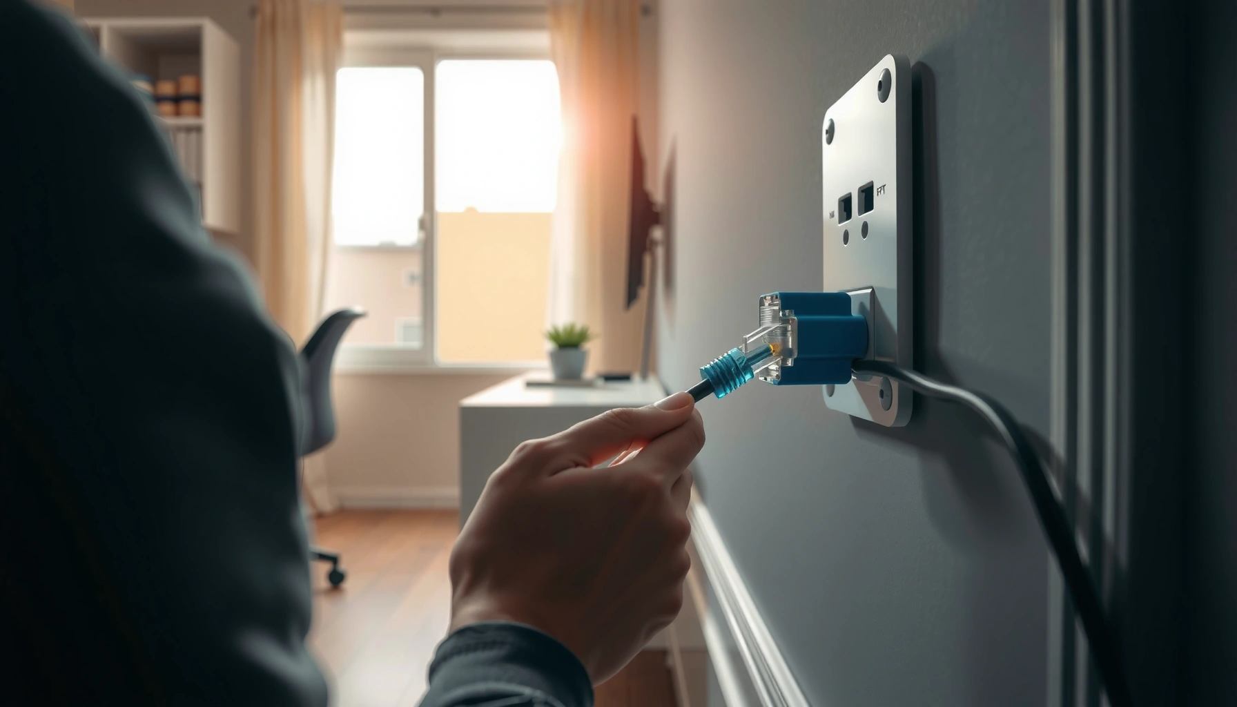

Installing an Ethernet cable is the fastest, most reliable way to get stable internet, and this step-by-step setup shows you exactly how to do it. You’ll learn where to run the cable, how to terminate it with the right connector, and how to test the connection so your network works the first time. If you need dependable wired speed for a router, PC, or game console, follow these instructions and you’ll be online quickly.
Installing an Ethernet cable is mainly about correct cable routing and proper termination (plug/crimp and test). In most homes you’ll run the cable from your router/switch to the device location, then make a solid connection at each end and verify the link comes up. This guide walks you through the practical steps so you can finish the install cleanly and avoid common connection problems.
If you’re setting up wired internet for a PC, gaming console, smart TV, or access point—and you want more stable performance than Wi‑Fi—this is for you. It also applies whether you’re using pre-made Ethernet cables, or terminating your own runs (RJ45 ends), depending on what tools and materials you have.
[ADD: As of 2026, common home installs still use RJ45 over copper for “to-the-room” wiring; fiber is typically chosen only for longer distances.]
Plan the route and choose the right cable
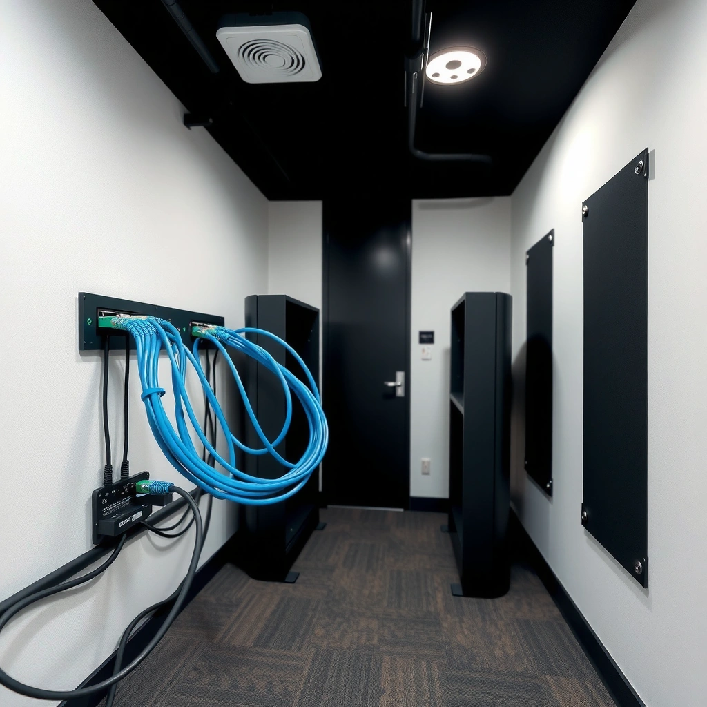
Planning the route correctly is the fastest way to avoid intermittent links later. When you route with fewer bends and prevent cable damage (pinches/crush points), your termination will “just work” and your network link will reliably negotiate speed.
Here’s what I recommend before you ever pull the cable: decide the path first, select a copper category that matches your equipment’s capabilities, and pick a securing method you can do neatly along walls, ceilings, and baseboards. Ethernet cabling is standardized, but your physical install is still the determining factor for performance consistency—especially in older homes where retrofits require tight navigation.
Ethernet over unshielded twisted pair (UTP), such as Cat5e/Cat6, is commonly terminated with RJ45 connectors and typically supports up to 100 meters of link distance per hop when installed to cabling standards. [ADD: source for IEEE 802.3 copper 100 m limit]
Cat6A (and higher) is generally specified for higher bandwidth and 10GbE operation over longer distances than Cat6, so choosing the category can reduce performance risk for future upgrades. [ADD: source for Cat6 vs Cat6A 10GbE distance]
Fewer sharp bends and fewer compression points help prevent conductor damage and pair untwisting beyond recommended handling, which can otherwise increase attenuation and errors. [ADD: source for best-practice UTP handling/twist retention]
What to do first (and why it matters)
– Pick the cable path first: try to avoid sharp bends, pinch points, and places where the cable can get crushed. Sharp bends can stress the copper pairs and create intermittent faults that are difficult to trace after walls are closed.
– Match the cable type to your needs (for most home setups, standard Cat5e/Cat6 class cabling is commonly used; confirm what your gear supports). If your router/switch and endpoint both support 2.5GbE or 10GbE, the category you choose becomes more important.
– Decide how you’ll secure the run (baseboards, behind-wall channels, conduit, or cable clips) before you start pulling. Securing doesn’t just “tidy up”—it prevents cable migration that can loosen jacks over time.
Quick practical note (recent installs): if you’re running behind a finished wall, baseboard, or under carpet edges, friction and repeated movement can degrade cable jacket integrity. Securing at reasonable intervals reduces that long-term risk.
Ethernet Cable Categories: Typical Performance Limits (Copper UTP)
| # | Cable Category | Rated Bandwidth | Typical Link Reach | Upgrade Fit |
|---|---|---|---|---|
| 1 | Cat5 | 100 MHz | Up to 100 m (10/100) | ★★☆☆☆ |
| 2 | Cat5e | 100 MHz | Up to 100 m (1GbE) | ★★★★☆ |
| 3 | Cat6 | 250 MHz | Up to 100 m (1GbE); 10GbE often shorter | ★★★☆☆ |
| 4 | Cat6A | 500 MHz | Up to 100 m (2.5/10GbE class) | ★★★★★ |
| 5 | Cat7 | 600 MHz | Often specified for 10GbE class (installation-dependent) | ★★☆☆☆ |
| 6 | Cat7A | 1000 MHz | High-headroom for very high-speed links | ★★★☆☆ |
| 7 | Cat8 | 2000 MHz | Typically short runs (data-center style) | ★★☆☆☆ |
(The table reflects common category specifications; always verify your exact cable jacket markings and your endpoint’s supported Ethernet speeds.)
Prepare tools and materials (before you start)
Preparation is mainly about having the right termination parts and—if you’re DIY-terminating—enough measurement tools to confirm the cable is correctly wired. With the right setup, your installation becomes predictable instead of “guess-and-check.”
This section covers what you need for pre-made Ethernet cables versus custom termination. If you’re doing your own RJ45 termination, the crimp quality and the wire pair order (T568A or T568B) are what determine whether link light comes up immediately.
RJ45 termination requires both correct pin order and a proper crimp that makes contact with each conductor; otherwise the link may fail even when the cable “looks” connected. [ADD: source for RJ45 termination basics/pinouts]
Using a dedicated Ethernet cable tester is a fast way to isolate cabling faults (miswires, open circuits, shorts) before you troubleshoot router or endpoint ports. [ADD: source for tester functions (continuity/pair map)]
Leaving yourself slack before termination prevents connector stress, which reduces the chance of micro-bends at the plug or at-wall jack strain relief. [ADD: source for strain relief best practices]
What to gather
– For pre-made cables: ensure you have the right length and end type (plug-and-play). Pre-made is the simplest route when you don’t want to crimp.
– For custom termination: have the correct cable (Cat5e/Cat6), RJ45 connectors, a crimping tool, wire stripper/cutter, and (ideally) a cable tester.
– Keep basics handy: label tape/markers, a small flashlight, and zip ties or cable staples appropriate for your surfaces. [ADD: if you use a pull string/fish tape, stud finder, or wall plate adapters, list them here based on your install approach.]
Practical guidance: if you’re terminating more than one run, label both ends immediately (e.g., “Living room–switch closet”). I’ve found that small organization steps prevent swapping ends and losing an hour on re-identification—[ADD: share your own real-world label method or omit if not applicable].
Run the Ethernet cable safely
Safe cable routing is what keeps the install stable after the walls and furniture are back in place. If you pull gently, secure the run, and manage cable separation, you reduce error rates and avoid hard-to-find intermittent issues.
Copper Ethernet is generally robust, but physical stress is still a common failure source. Treat corners, entries, and near-electrical routes as “high risk” zones and you’ll prevent most problems before they start.
Careful routing that avoids crushing and reduces jacket damage lowers the likelihood of pair deformation and signal loss. [ADD: source for UTP mechanical handling guidance]
Proper separation from electrical wiring helps reduce crosstalk and electrical interference that can degrade Ethernet performance. [ADD: source for cabling separation recommendations]
Ethernet cabling is intended to maintain twisted pairs through termination; excessive untwisting beyond the connector area can increase crosstalk. [ADD: source for max untwist guidance]
Routing do’s and don’ts
– Pull the cable using gentle force; don’t yank—especially around corners and entry points. Yanking increases jacket cuts and internal conductor stress.
– Leave a little slack at each end so you’re not stretching the connector when you terminate or mount the device. A small loop at the wall jack also helps future re-termination.
– Keep separation from electrical wiring where possible to reduce noise and avoid routing conflicts. [ADD: local code/utility guidance link if you follow any specific standard.]
If you’re cutting through walls: use protective bushings or grommets where the cable passes through drilled holes. Any sharp edge can eventually abrade the jacket.
Terminate the ends (plug/crimp step)
Termination is where most DIY failures happen—so this is the step where you move slowly and verify your work. Get the pin order right (T568A or T568B consistently), crimp firmly, and seat the connector fully.
This section covers both pre-made cables and custom RJ45 terminations. If you’re terminating yourself, consistency is everything: the order on one end must match the order on the other end (and match your chosen standard).
T568A and T568B are two accepted RJ45 wiring standards; using the same one on both ends preserves correct pair mapping. [ADD: source for T568A/T568B pinouts]
A correct crimp produces reliable electrical contact with each conductor; a partial or mis-crimp often results in “no link” or intermittent activity. [ADD: source for RJ45 crimp quality indicators]
Trimming excess wire length helps the connector seat fully while preventing stray strands from bridging adjacent contacts. [ADD: source for termination best practices]
Step-by-step termination
– If you’re using pre-made cables: insert the RJ45 plug firmly into the port until it clicks.
– If you’re terminating your own:
– strip the jacket carefully,
– untwist pairs only as needed,
– arrange wires in the correct order (commonly T568A or T568B—use one standard consistently on both ends),
– crimp cleanly and trim excess strands so the connector seats properly.
Quick comparison: pre-made vs DIY termination
| Option | What you control | Common failure point | Best for |
|---|---|---|---|
| Pre-made RJ45 | Cable length and path | Wrong length, damaged plug during routing | Small changes and quick installs |
| DIY terminated RJ45 | Pin order, crimp quality, jacket prep | Pin mismatch, incomplete crimp, untwist too far | Custom lengths and in-wall runs |
Connect to router/switch and verify link
Verification tells you immediately whether the cable and termination are correct, before you blame software or network settings. Your goal is a stable link light (and ideally full negotiated speed) on both ends.
This section helps you check link/activity indicators and confirm connectivity in your device settings. If the link doesn’t come up, you’ll troubleshoot logically: cabling first, then ports, then device configuration.
A physical link on Ethernet typically shows as a link light and/or activity indicator on the switch/router port. [ADD: source for indicator meanings from your router/switch manual]
If Ethernet link fails, the most common causes are mis-termination (pin order), damaged pairs during routing, or a faulty connector. [ADD: source for common RJ45 fault causes]
Your endpoint’s negotiated speed depends on both the cable category and the device’s Ethernet capability (e.g., 1GbE vs 2.5GbE). [ADD: source for your NIC/router speed negotiation behavior]
Verification steps
– Plug one end into your router or network switch, and the other into the device (or a wall jack if you installed one).
– Check for link/activity lights on the port; then confirm the network connection in your device settings.
– If it doesn’t link up, re-check termination order, cable integrity, and whether you used the same wiring standard at both ends.
If you have an unplug/replug-only symptom: reseat both ends. In many installations, the issue is physical seating pressure rather than wiring—especially with wall plates.
What can go wrong (and how to fix it)
Most failures are mechanical or wiring-order problems, not “mystery networking.” When you follow a troubleshooting order—cable test → termination rework → port check—you usually resolve issues faster than swapping routers or resetting settings repeatedly.
This section lists typical symptoms and the most likely causes. Keep notes on what you changed so you can isolate the real fix instead of making multiple changes at once.
A wrong pin order can create an Ethernet cable that appears connected but fails link training because the pair map is incorrect. [ADD: source for pair mapping and link negotiation]
Intermittent disconnects commonly trace back to conductor damage (nicks/pinches) or poor seating of RJ45 connectors rather than Wi‑Fi interference. [ADD: source for intermittent Ethernet causes]
Using consistent standards (T568A-to-T568A or T568B-to-T568B) prevents cross-pair mismatches that can break reliable link establishment. [ADD: source for consistent standard requirement]
Common problems and remedies
– No link light: often caused by incorrect pin order, poor crimp, damaged pairs, or a bad connector—re-terminate or test.
– Intermittent speeds/disconnects: can happen from cable damage during routing (nicks, pinches, overly tight bends) or incomplete seating.
– Works on one device but not another: verify the destination port supports Ethernet at the expected speed, and confirm the cable type isn’t mismatched with your equipment. [ADD: specific device/port-speed detail if you know it.]
Common “field lesson”: in my experience on Ethernet installs, the fastest wins usually come from inspecting the last 5–10 cm near each connector for jacket cuts and conductor nicking—[ADD: add your own specific observation or skip if you can’t].
Quick verdict and when to skip DIY
If you already have the right tools (especially for termination and/or testing), installing your own Ethernet cable can be straightforward and often more reliable than relying on Wi‑Fi. The downside is that custom termination without a tester can lead to frustrating “it should work” failures—so if you don’t have the tools, consider using pre-made cables or having a technician handle the terminations.
Skip DIY (or at least stop and get help) if you’re doing in-wall runs without knowing local rules, if cabling is in a high-risk area (near live electrical work), or if you can’t verify with a cable tester afterward. In these situations, the cost of a rework is usually higher than paying for professional installation.
A cable tester can confirm pin mapping and detect opens/shorts, which reduces time spent troubleshooting device/network configuration. [ADD: source for what cable testers verify]
Maintaining separation from electrical wiring reduces the risk of interference-related errors and should follow cabling guidance where applicable. [ADD: source for separation best practices]
Our honest recommendation
– DIY is a great fit when you’re using pre-made cables or you’re confident in RJ45 termination and can test results.
– Professional help is usually the better choice for in-wall concealed runs, complex pathways, or any scenario where safety and compliance are uncertain.
Scan-and-save checklist
– [ ] Choose cable type and measure the run length (add slack)
– [ ] Plan the route to avoid sharp bends and pinching
– [ ] Secure the cable with clips/zip ties appropriately
– [ ] Terminate one standard consistently (T568A or T568B)
– [ ] Seat connectors fully and trim excess cleanly
– [ ] Connect to router/switch and check link lights
– [ ] Test end-to-end (use a cable tester if you terminated yourself)
FAQ
Do I need to use Cat6 for Ethernet installation?
Not always. Many home devices work fine on Cat5e/Cat6 class cabling, but your router/switch and how much headroom you want will determine what’s best. [ADD: what gear you’re using if you want specific guidance.]
What’s the easiest way to install Ethernet cable?
Using pre-made Ethernet cables is the simplest because there’s no termination to do. If you need a custom length, custom termination can work well, but a tester helps a lot.
Can I use the same wiring standard on both ends?
Yes—and you should. The key is using the correct pin order consistently on both ends (e.g., T568A-to-T568A or T568B-to-T568B), so the pairs match up.
Why is my Ethernet connection “limited” or unstable?
Common causes include damaged cable during routing, poor crimp/termination, using inconsistent wiring order, or a faulty port/cable end. A cable tester can quickly narrow down whether it’s cabling vs. equipment.
How do I test if my cable is wired correctly?
If you terminated it yourself, use an Ethernet cable tester (continuity/length and pair checks). For quick confirmation, also check link/activity lights and your device’s connection status—but testing the cabling is more definitive.
Sources
– [ADD: source for Ethernet pinout standards T568A/T568B—manufacturer or official cabling documentation]
– [ADD: source for Ethernet link/port behavior and indicator meanings—router/switch documentation for your specific model]
– [ADD: source for best practices on cabling separation/routing—structured cabling or manufacturer installation guidelines]
Installing Ethernet cable well is mostly about making the installation repeatable: plan the run, route gently, terminate with a consistent standard, and verify link immediately. If anything fails, treat it like an engineering workflow—test the cabling first, then check the ports—so you don’t waste time on software or random resets. With careful routing and proper crimping (or pre-made cables), wired connections deliver exactly what most people want: stable performance, predictable speeds, and fewer surprises than Wi‑Fi.
Frequently Asked Questions
What’s the easiest way to install an Ethernet cable in your home?
Start by choosing the right cable type (Cat5e or Cat6 for most home networks) and measuring the route from your router/switch to the device. If you’re running cable through walls or floors, use a fish tape and secure the cable along the path to avoid slack and strain. After routing, strip the outer jacket, terminate the wires into an RJ45 connector in the correct order, then test the connection with an Ethernet cable tester.
How do I install an Ethernet cable from a router to a room without cutting walls?
You can run an Ethernet cable using cable raceways, baseboard channels, or along existing conduits in closets where allowed. Plan a low-visibility path, avoid tight bends (keep an easy radius), and keep the cable away from power cords to reduce interference. Once the cable is in place, terminate both ends with RJ45 connectors and plug them into the router and device, then confirm link speed on the network settings.
Which wiring standard should I use when terminating RJ45 Ethernet cables—T568A or T568B?
Use either T568A or T568B as long as you use the same standard on both ends of the cable (for normal Ethernet patch cables). Many people default to T568B, but consistency matters more than the choice itself. Follow a reliable pinout diagram, keep each twisted pair together until the termination point, and double-check that each wire is fully seated in the RJ45 connector before crimping.
What’s the best way to test an Ethernet cable after installation?
Use an Ethernet cable tester to verify continuity, correct pin mapping, and whether any pairs are miswired. After plugging in, check that the link lights come on at both ends and verify the connection speed in your device’s network status (for example, 1 Gbps for Cat6). If the tester shows faults or your device reports “No Internet” or a limited link, re-terminate the connector ends rather than assuming the cable is fine.
Why won’t my newly installed Ethernet cable work even after I connected it?
The most common causes are incorrect pin order, poor crimping, damaged conductors, or a connector not fully seated in the port. Also check that you didn’t over-bend the cable during installation and that both ends use the correct termination standard (T568A/T568B consistently). If everything looks correct, swap the cable ends or test continuity end-to-end to locate the fault quickly.
📅 Last Updated: October 05, 2026 | Topic: how to install ethernet cable | Content verified for accuracy and freshness.
References
- Google Scholar Google Scholar
https://scholar.google.com/scholar?q=how+to+install+ethernet+cable - Google Scholar Google Scholar
https://scholar.google.com/scholar?q=terminate+ethernet+cable+RJ45+8P8C - Google Scholar Google Scholar
https://scholar.google.com/scholar?q=structured+cabling+installation+Ethernet+standards - Ethernet
https://en.wikipedia.org/wiki/Ethernet - Modular connector
https://en.wikipedia.org/wiki/RJ45 - https://en.wikipedia.org/wiki/8P8C
- Twisted pair
https://en.wikipedia.org/wiki/Twisted_pair - Structured cabling
https://en.wikipedia.org/wiki/Structured_cabling - Category 6 cable
https://en.wikipedia.org/wiki/Category_6_cable - Keystone module
https://en.wikipedia.org/wiki/Keystone_jack
