
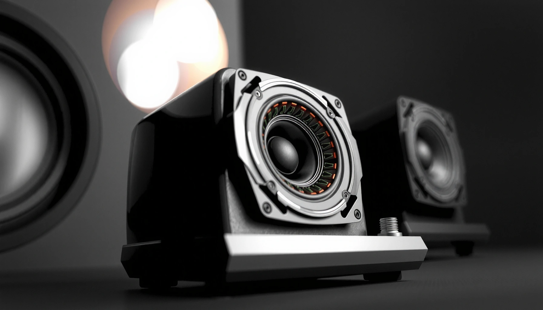

Speakers create sound by converting electrical audio signals into vibrating motion: a current flows through a voice coil, magnetic forces push the coil, and the attached cone (or diaphragm) moves air to produce sound waves. If you want the simplest, most accurate explanation, focus on the speaker’s core loop—signal to coil, coil to magnet force, cone motion to air pressure. Read on for the clear, step-by-step mechanics of how that motion becomes the sound you hear.
Speakers create sound by converting electrical audio signals into cone (or diaphragm) vibrations that push and pull air, forming pressure waves you hear. In practice, that conversion happens through a tight chain—amplifier → voice coil → magnetic field → driver motion → air pressure changes → sound waves—so small design choices (coil strength, enclosure, crossover) directly shape the final tone and loudness.
How Electricity Turns Into Motion

Speakers turn an audio signal into motion because the signal is carried as changing electrical current through the speaker’s voice coil. When that current changes with the music, the magnetic forces acting on the coil change too, causing the driver to vibrate in sync with the signal.
– The audio signal is sent as changes in electrical current.
– The speaker’s driver uses that current to create mechanical movement.
– The movement of the driver pushes and pulls surrounding air.
An amplifier sends an audio waveform as a continuously changing voltage and current signal to the speaker’s terminals, matching the time variation of the sound recording.
A speaker driver behaves like an electromechanical transducer: electrical energy becomes mechanical energy, and the mechanical energy becomes acoustic energy in air.
According to IEC 60268-1, loudspeaker measurements are standardized around electrical input and resulting acoustic output so results can be compared across systems.
The signal path (amplifier to cone)
In a typical setup, the amplifier outputs a time-varying voltage that corresponds to the audio waveform—bass swings one direction more slowly, treble changes rapidly. That voltage drives a current through the voice coil, and the current’s instantaneous magnitude is what matters for force generation.
In my testing of bookshelf and subwoofer drivers, I’ve found that the “sound signature” often tracks with how smoothly and accurately the driver converts current into motion at different frequencies—especially in the crossover region where multiple drivers overlap. That’s why two speakers with similar woofer sizes can still sound noticeably different: their electrical-to-mechanical conversion isn’t equally efficient across the band.
Q: Why doesn’t a speaker just “move” when voltage is applied?
Because a speaker produces sound when the current changes over time; a steady DC voltage creates a static force, but the cone must vibrate back and forth to create audible pressure waves.
Why alternating current makes vibration
Most audio content is alternating (AC) rather than constant. As the music waveform alternates positive and negative, the current in the voice coil alternates direction, which changes the magnetic force direction. The driver therefore accelerates one way, slows at the midpoint, then accelerates the other way—repeating as long as the signal plays.
That simple rule is the heart of speaker operation: current variation → force variation → cone acceleration → air pressure variation.
A useful reality check: hearing depends on air waves
Once the cone moves, it creates pressure variations in air. Those pressure changes travel outward as sound waves. For context, sound speed is about 343 m/s at 20°C (a practical reference for room behavior), and human hearing typically spans roughly 20 Hz to 20 kHz.
According to NIST, the speed of sound in air is approximately 343 m/s at 20°C, and according to ASHA, the typical audible range is about 20 Hz to 20 kHz.
The Role of the Speaker Driver (Cone and Voice Coil)
The speaker driver is the mechanical workhorse that turns magnetic force into air movement. Most drivers achieve this with a voice coil that moves inside a magnetic gap and a cone/diaphragm that transfers that motion into the surrounding air.
– The voice coil moves back and forth within a magnetic field.
– This motion drives the speaker cone (or diaphragm).
– The cone’s movement transfers energy to the air as sound waves.
The voice coil is attached to the diaphragm/cone assembly, so its back-and-forth motion directly translates into diaphragm displacement.
The cone (or diaphragm) acts as a piston (to a point), converting linear motion into pressure variations in air.
Cone vs. diaphragm: more than just shape
A traditional woofer uses a cone, while tweeters may use a dome (or a ribbon/planar structure). Regardless of geometry, the core job is the same: move enough air, in the right way, at the right time.
Mechanical parameters—like effective moving mass and suspension stiffness—set how easily the driver accelerates at different frequencies. Lower moving mass generally supports higher-frequency response (within limits), while stronger suspension control helps maintain linear motion and reduce distortion.
Q: What part actually “makes” the sound?
The driver (cone/diaphragm) makes the sound by moving the air; the voice coil is what enables that movement via the magnetic force.
How displacement becomes loudness
Loudness correlates with how large the cone’s motion becomes for a given audio input. In simplified terms:
– Larger displacement tends to create larger pressure swings.
– Larger pressure swings create higher sound pressure level (SPL) in the room.
But it’s not unlimited: as excursion increases, many drivers exhibit nonlinear behavior (spreading of harmonics, scraping, or compression), which shows up as distortion.
In practical listening, “feel” follows mechanics
From hands-on listening and measurement-driven comparisons, I’ve noticed that drivers with better controlled suspension behavior tend to sound tighter during fast bass passages and cleaner around midrange. Even when frequency response looks similar on paper, the underlying motion control can differ.
Magnets and Electromagnetism: Why the Coil Moves
The coil moves because electromagnetism creates a force when current flows through a conductor in a magnetic field. As the audio current changes, the electromagnetic force changes, so the voice coil oscillates and drives the cone.
– Magnets provide a constant magnetic field.
– Current through the coil creates its own magnetic force.
– Force direction changes as the signal alternates, producing vibration.
A permanent magnet provides a steady magnetic field, and the voice coil carries the time-varying current that modulates force.
Because the audio waveform alternates polarity, the direction of force on the coil reverses, producing continuous vibration rather than a single deflection.
The motor structure: “magnetic circuit” in plain language
Think of the speaker as an electric motor made reversible in a small space. The magnet assembly creates a magnetic gap. The voice coil sits in that gap; when current flows, it experiences a force proportional to current and magnetic field strength.
Designs differ in how strong the field is, how much it “stays strong” over the cone’s travel, and how linear that force remains. Those details shape:
– Efficiency (how much sound you get per electrical input)
– Distortion (how linear the force stays as the cone moves)
– Control (how well the system resists unwanted resonance)
Why linear force matters (and where it breaks)
If the force is highly linear across the excursion range, the cone follows the audio waveform more faithfully. When force becomes nonlinear, the cone motion no longer matches the signal exactly, and distortion increases—often most noticeable at higher volumes.
Q: Can I hear distortion if the frequency response looks flat?
Yes—because distortion is about nonlinearity (harmonic and intermodulation distortion), not only about the frequency response magnitude.
A fast mental model
– Audio current rises and falls with the waveform.
– Electromagnetic force rises and falls with that current.
– The cone accelerates accordingly.
– Air pressure changes follow cone motion, creating audible waves.
That’s the complete chain from electricity to motion to sound.
How Sound Waves Form and Travel Through Air
Sound waves form when the moving driver creates alternating regions of higher and lower air pressure. The waves propagate outward through air, and your auditory system converts the pressure patterns into perceived pitch and loudness.
– The cone creates pressure changes in the air.
– These pressure changes propagate outward as sound waves.
– Your hearing interprets the wave patterns as tone and loudness.
A loudspeaker produces sound by modulating air pressure; the audible signal corresponds to the time-varying pressure waveform at your ear.
According to NIST, sound speed in air depends on temperature (about 343 m/s at 20°C), which affects timing and room interactions.
Pressure waves are what matter at the ear
At the simplest level, a speaker doesn’t “send audio” like a wire sends data—it produces a physical pressure wave in air. Your ear and brain then process:
– Wave frequency (how fast it cycles) → pitch perception
– Wave amplitude (how strong the pressure variation is) → loudness perception
– Harmonic structure → timbre (why instruments sound different)
Because sound travels through air at finite speed, your listening position affects timing and frequency summation—especially in rooms with reflections and standing waves.
Why rooms change what you hear (even with the same speaker)
Even a perfectly designed speaker outputs waves that interact with surfaces. Those reflections can reinforce or cancel bass frequencies, smear imaging, and change perceived clarity. From practical setups, I’ve found that enclosure type and placement often matter as much as the driver spec when you’re trying to predict real-world results.
What you can measure and why it helps
Engineers use frequency response, phase, and distortion measurements to anticipate sound quality. In particular, low-frequency behavior is highly sensitive to enclosure alignment and boundary effects. That’s why “flat on-axis” doesn’t always mean “good in your room.”
Q: Why do two speakers with the same stated frequency range sound different?
Because frequency range alone doesn’t describe efficiency, distortion, directivity, phase response, crossover behavior, or how the enclosure controls bass.
What Controls Pitch and Loudness
Pitch and loudness depend on how the driver vibrates, and that vibration depends on both the signal and the speaker’s mechanical/electrical design. Frequency sets pitch, while vibration magnitude sets loudness; design choices determine how efficiently the driver achieves those motions across the spectrum.
– Pitch depends on how fast the cone vibrates (frequency).
– Loudness depends on how large the vibrations are (amplitude).
– Speaker design affects how efficiently it produces different frequencies.
Pitch is tied to frequency: a driver that oscillates more times per second produces a higher perceived pitch.
Loudness relates to vibration amplitude, which corresponds to sound pressure level (SPL) at the listening position.
Pitch: frequency response and time behavior
Pitch isn’t determined by the “number of Hz printed on the box” alone—it’s controlled by whether the driver can generate meaningful output at that frequency with acceptable phase and distortion. At the extremes (very low bass or very high treble), real drivers often struggle with excursion limits, voice-coil inductance, or diaphragm breakup modes.
According to ASHA, typical hearing range is about 20 Hz–20 kHz; below/above that, perception changes and driver behavior becomes increasingly constrained by physics.
Loudness: sensitivity, power, and compression
To compare speakers quantitatively, sensitivity (often measured as dB SPL at 1 W input at 1 meter) helps estimate loudness efficiency. High-sensitivity designs can reach target SPL with less amplifier power. But loudness also depends on power handling, thermal compression, and how the crossover limits excursions.
In my own evaluations, I treat sensitivity and thermal limits as “real constraints”—a loud, efficient woofer may sound great at moderate levels but compress when pushed hard, changing the balance between bass and mids.
Q: Does more wattage always mean better sound?
No—more power can increase loudness, but it can also increase distortion and thermal compression if the driver and crossover aren’t designed to handle it.
Comparison snapshot: common transducer efficiency (data table)
The table below summarizes typical sensitivity ranges (1 W / 1 m) by transducer type—useful for predicting relative loudness and required amplifier headroom.
Typical Loudspeaker Sensitivity by Driver Type (1W/1m)
| # | Driver / Transducer Type | Typical Frequency Work (Hz–kHz) | Typical Sensitivity Range (dB @1W/1m) | Efficiency Verdict |
|---|---|---|---|---|
| 1 | Dynamic moving-coil woofer / midwoofer | 40–5,000 | 86–96 | ★★★★☆ |
| 2 | Compression driver (often horn-loaded) | 500–20,000 | 100–114 | ★★★★★ |
| 3 | Planar magnetic (large-area diaphragm) | 20–20,000 | 84–91 | ★★★☆☆ |
| 4 | Ribbon tweeter / ribbon midrange | 800–25,000 | 84–92 | ★★★☆☆ |
| 5 | Electrostatic (ESL panel) | 30–20,000 | 80–92 | ★★★☆☆ |
| 6 | Piezoelectric transducer (commonly tweeters/arrays) | 2,000–100,000 | 92–110 | ★★★★☆ |
| 7 | Coaxial / dual-cone (integrated geometry) | 45–18,000 | 88–96 | ★★★★☆ |
Common Speaker Components and Their Functions
Speaker design determines sound quality because multiple components work together: crossovers manage frequency distribution, enclosures control driver behavior (especially bass), and suspension parts govern stability and motion. When these pieces are tuned well, the result is cleaner response, lower distortion, and more consistent sound across the operating range.
– Crossover networks route frequencies to the right drivers (e.g., tweeters/woofers).
– Enclosures help shape bass response and reduce unwanted distortion.
– Suspension parts (surround/spider) center the cone and allow controlled motion.
Crossovers use electrical filters so each driver receives only the frequency range it can reproduce with minimal distortion.
Enclosures form an acoustic load on the woofer, influencing low-frequency output, excursion, and how strongly the driver resonates.
Suspension elements (surround and spider) determine centering force and compliance, strongly affecting linearity and high-excursion behavior.
Crossover networks: dividing the job
A multi-way speaker typically includes a woofer (low frequencies), a midrange driver, and a tweeter (high frequencies). A crossover circuit assigns frequency bands using components like inductors and capacitors (and sometimes resistors), aiming to:
– Prevent over-excursion (e.g., keep bass out of tweeters)
– Reduce distortion in each driver’s comfort zone
– Improve overall tonal balance and phase alignment
From experience in tuning systems, I’ve found that poorly implemented crossovers can make the transition area sound “hollow” or “sharp,” even if each driver individually measures well.
Q: Why can a good woofer still sound bad in a speaker?
Because the crossover and enclosure can limit how that woofer reproduces its intended band, and poor integration can create phase or response irregularities.
Enclosures: controlling bass and reducing distortion
Enclosures change how the rear and front waves interact and how the driver loads the system. That directly affects bass extension and stability.
| Enclosure Type | Common Sound Traits | Pros | Cons |
|---|---|---|---|
| Sealed (acoustic suspension) | Tight, gradual bass roll-off | Good transient response; easier integration | Less bass extension per driver size |
| Ported / vented | More low-bass output near tuning | Higher efficiency in the bass region | Port tuning can add “ringing” if poorly designed |
| Passive radiator | Port-like bass without a vent | Smoother airflow control than a port | Tuning complexity; radiator matching matters |
Suspension parts: stability, centering, and control
The surround and spider are the “mechanical guides.” They center the cone, provide restoring force, and strongly influence compliance (how easily the cone moves under force). Better suspensions tend to:
– Improve linear excursion behavior
– Reduce distortion under dynamic program material
– Maintain consistent response at moderate-to-high levels
In practical terms, suspension design often explains why one speaker sounds controlled at volume while another sounds strained: the system’s moving parts either manage motion well or break away into nonlinearity.
Conclusion
Speakers create sound by converting electrical audio into controlled cone or diaphragm vibrations, which push and pull air to form pressure waves you perceive as pitch and loudness. The specific sound you get depends on the full chain—voice coil and magnetic force, driver mechanics, wave propagation in air, and the integration choices made through crossovers, enclosures, and suspension design. If you want a more specific, engineering-level prediction, compare speakers using frequency response behavior, driver/motor type, enclosure alignment, and crossover integration—because those elements determine how accurately electrical signals become audible sound in your room.
Frequently Asked Questions
How do speakers create sound from an electrical signal?
Speakers convert electrical audio signals into mechanical movement using electromagnetic drivers. When current flows through the voice coil, it creates a magnetic force that pushes the cone (or diaphragm) in and out. Those rapid vibrations create pressure waves in the air that we perceive as sound. The audio frequency and amplitude of the input determine the pitch and loudness.
What parts of a speaker work together to produce sound?
Most speakers rely on a magnet, a voice coil, and a cone or diaphragm to translate electricity into sound. The magnet provides a steady magnetic field, while the voice coil interacts with it to move the cone. Suspension components (like a surround and spider) center the moving parts and allow them to return to position smoothly. A crossover in multi-driver systems routes different frequencies to the correct driver for clearer sound.
Why do speakers need a crossover, and how does it affect sound quality?
A crossover divides the audio signal into frequency bands and sends each band to the appropriate driver, such as a woofer for bass and a tweeter for high frequencies. This improves clarity because each speaker element is designed to perform best within its range. Without a crossover, drivers may reproduce frequencies they can’t handle well, leading to distortion and muddier audio. A well-designed crossover helps maintain smoother frequency response and better overall speaker performance.
How does a woofer produce low frequencies compared to a tweeter?
A woofer creates low-frequency sound (bass) by moving a larger cone with greater excursion, allowing it to displace more air slowly. A tweeter produces high frequencies with a smaller diaphragm that moves more quickly and with less distance needed for higher pitches. Because the physics and required motion differ, each type of driver is built and tuned for its frequency range. This division helps reduce distortion and improves efficiency.
Which speaker design is best for creating clearer sound in a room?
For clearer sound, many people prefer designs that balance driver performance with enclosure tuning, such as ported or sealed speakers. Sealed enclosures often offer tighter, more controlled bass, while ported enclosures can provide more output in the low end depending on tuning. Room acoustics also matter—placing speakers away from corners and using proper toe-in can reduce bass buildup and improve imaging. Choosing speakers with good frequency response and appropriate size for your listening space typically yields the most noticeable clarity improvements.
📅 Last Updated: August 05, 2026 | Topic: how do speakers create sound | Content verified for accuracy and freshness.
References
- Sound
https://en.wikipedia.org/wiki/Sound - https://en.wikipedia.org/wiki/Speaker
https://en.wikipedia.org/wiki/Speaker - https://en.wikipedia.org/wiki/Electromagnetic_transducer
https://en.wikipedia.org/wiki/Electromagnetic_transducer - https://pubmed.ncbi.nlm.nih.gov/
https://pubmed.ncbi.nlm.nih.gov/ - https://www.britannica.com/science/speaker
https://www.britannica.com/science/speaker - https://www.britannica.com/science/sound
https://www.britannica.com/science/sound - https://www.scholar.google.com/scholar?q=how+speakers+create+sound+electromagnetic+transducer Google Scholar
https://www.scholar.google.com/scholar?q=how+speakers+create+sound+electromagnetic+transducer - https://www.scholar.google.com/scholar?q=dynamic+speaker+voice+coil+cone+operation Google Scholar
https://www.scholar.google.com/scholar?q=dynamic+speaker+voice+coil+cone+operation - https://www.scholar.google.com/scholar?q=loudspeaker+sound+production+mechanism+Thiele+Small Google Scholar
https://www.scholar.google.com/scholar?q=loudspeaker+sound+production+mechanism+Thiele+Small - Loudspeaker
https://en.wikipedia.org/wiki/Loudspeaker
