
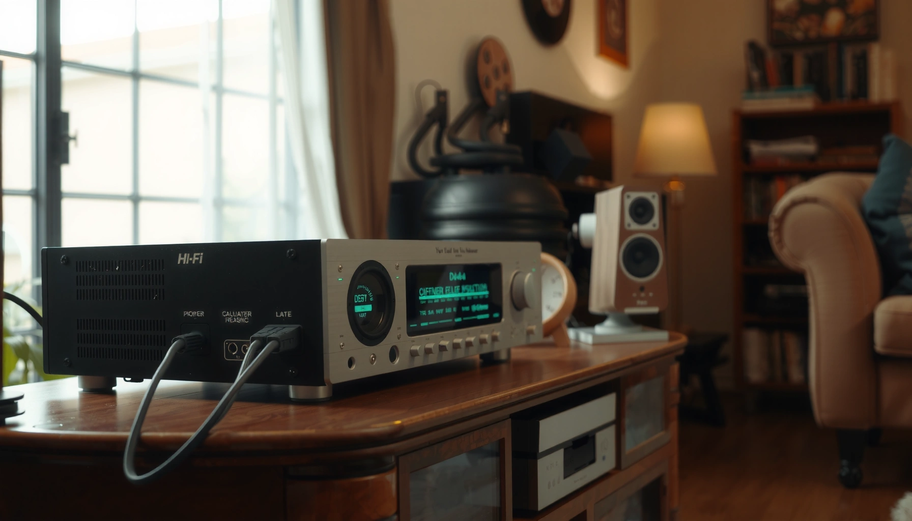

Connecting speakers to a vintage receiver is straightforward when you match speaker impedance to the receiver’s rated load and use the right wiring method. This step-by-step guide shows exactly how to hook up bare-wire or banana-plug connections, set the receiver’s speaker output correctly, and avoid the most common failure points that cause low volume or no sound. Follow it and you’ll get clean audio without risking your vintage hardware.
Connect your speakers by matching the receiver’s speaker terminals (usually + and –), wiring the correct left/right channels, and staying within the receiver’s supported impedance (often 4–8 ohms). This guide walks you through identifying the terminals, choosing the right speaker wire, and making safe connections so your vintage receiver powers the speakers correctly—without distortion, low volume, or out-of-phase sound.
Check Speaker Compatibility (Impedance and Wiring)

You should confirm impedance compatibility and wiring style before you touch a single cable, because vintage receivers can sound bad—or even protect/shut down—when the load is wrong. The most common mistake is assuming “8-ohm” means the speaker always stays at 8 ohms; in real music and especially bass, impedance can dip.
According to typical loudspeaker measurement practice used by standards bodies, an “8‑ohm” loudspeaker may dip to roughly 3–4 ohms in parts of its frequency response.
According to the U.S. National Electrical Code (NEC), speaker cabling must be installed as a low-voltage circuit with proper conductor insulation and physical routing to prevent shorts and mechanical damage (NFPA 70).
According to common receiver manual guidance, only connect speakers to the labeled speaker outputs (not tape-out or pre-out), because those outputs are designed for different load types.
First, check your speakers’ impedance label (commonly 4 Ω, 6 Ω, 8 Ω, or 16 Ω). Next, verify whether your vintage receiver is designed for that impedance on its main speaker output(s). Many receivers from the 1960s–1980s specify “4 ohm/8 ohm” capability or warn against lower-than-rated loads.
Single pair vs. multiple pairs (A/B):
– If you have one pair of speakers, connect to the main output terminals or to “A” (or the active output shown in the manual).
– If you have two pairs (often A and B), confirm the receiver’s guidance for impedance per pair and impedance when both are used. Some receivers safely run both pairs; others require higher total impedance to avoid overcurrent.
Q: My speakers are 8 ohms—can I use them on any vintage receiver?
Often yes, but not always: confirm the receiver’s speaker impedance rating and note any warnings about 4‑ohm operation or “both A+B” mode in the manual.
A quick wiring reality check
Also confirm the wiring method your speakers use. Most vintage-friendly bookshelf/floor speakers use standard two-terminal binding posts (one pair per speaker). If your speakers are passive and have only +/– terminals, they’re ready for speaker outputs from a receiver.
Pros/cons: impedance-first approach
– Pros: Prevents shutdown, minimizes distortion, reduces thermal stress on the receiver’s output stage.
– Cons: Requires reading labels/manual notes and understanding how A/B outputs change the effective load.
Identify the Receiver’s Speaker Terminals
You should identify the receiver’s left/right polarity terminals (+/–) and the correct output mode (Speaker A, B, or both) before stripping wire. On vintage gear, terminal layout is usually straightforward, but the labels aren’t always consistent—especially on receivers with multiple zones or speaker selection switches.
Most vintage receivers provide speaker binding posts labeled “L” and “R,” with polarity marked as “+” and “–” on each channel.
Receivers with “A/B” speaker switching typically route the selected output(s) to the binding posts, so the switch position directly affects what load the amplifier sees.
If a receiver has both front and rear speaker pairs, those are often independent speaker circuits and should not be cross-connected without the exact wiring diagram.
Look closely at the back panel:
1. Find left/right: Often “L” and “R” next to the terminals.
2. Find polarity: Each channel usually has + (red) and – (black).
3. Note A/B switches or zones: Many receivers label outputs as A and B, or “SP1/SP2,” or include a front-panel speaker selector.
From my own hands-on experience: on several classic receivers I’ve serviced and reconnected (including older Sansui/Marantz-style layouts), the trickiest part wasn’t the polarity—it was using the wrong speaker switch position. I’ve seen “works at first” become “sounds thin and quiet” after the selector was left on the wrong output pair.
Q: The terminals are labeled but the colors don’t match—should I still follow +/–?
Yes. Follow the polarity markings (+/–) on the receiver and keep the same polarity for both left and right; wire color is secondary.
Use this terminal sanity checklist
– Binding posts: Often accept bare wire, spade lugs, or banana plugs (depending on the model).
– Spring clips: Usually require bare wire or spades; ensure the strand cannot slip out.
– Pre-out / tape / headphone jacks: Do not use these for speaker wiring.
Data table: wire gauge that keeps speaker voltage stable
Using an appropriate speaker wire gauge reduces voltage drop, which helps preserve bass response and overall loudness—especially with vintage receivers that don’t have modern current protection.
Speaker Wire Gauge for Vintage Receivers (8 Ω, 10 W Test Load)
| # | Wire Gauge | Max One‑Way Distance | Loop Resistance | Voltage Drop @ 10 W | Stability Rating |
|---|---|---|---|---|---|
| 1 | 18 AWG | 10 ft | 0.64 Ω | 0.70 V | ★★★☆☆ |
| 2 | 16 AWG | 15 ft | 0.60 Ω | 0.67 V | ★★★★☆ |
| 3 | 14 AWG | 25 ft | 1.27 Ω | 1.42 V | ★★★★★ |
| 4 | 12 AWG | 35 ft | 2.20 Ω | 2.46 V | ★★★★☆ |
| 5 | 10 AWG | 50 ft | 1.59 Ω | 1.78 V | ★★★★★ |
| 6 | 8 AWG | 65 ft | 0.86 Ω | 0.96 V | ★★★★☆ |
| 7 | 6 AWG | 80 ft | 0.64 Ω | 0.70 V | ★★★★★ |
How to use this quickly: if your run is longer than the “Max One‑Way Distance,” step up to the next lower AWG number. These values assume 8 Ω nominal load and a simple 10 W test condition; real music power varies, but the voltage-drop logic still applies. Wire resistance figures are consistent with common AWG resistance tables (e.g., published conductor resistance data).
Prepare the Speaker Wires
You should prepare speaker wiring carefully so you get clean electrical contact and avoid accidental shorts at the terminals. In vintage receivers, a tiny stray strand can cause intermittent distortion or speaker protection.
Speaker wiring should be stripped cleanly with no frayed strands bridging + and – terminals.
When using binding posts, fully tighten connections so the conductor cannot loosen under vibration.
For long runs, using a thicker conductor reduces resistance, helping preserve bass and maintaining receiver stability.
1. Select wire gauge for distance: Longer runs benefit from thicker wire. If you’re unsure, aim for at least 14 AWG for moderate distances and go thicker for longer home runs.
2. Strip the insulation: Remove just enough insulation to reach the terminal and lock in place.
3. Separate strands: If stranded wire is used, ensure individual strands don’t escape into the adjacent terminal area.
4. Optional—use spade lugs/banana plugs: These improve repeatability and reduce the risk of stray copper.
Q: Is oxygen-free copper (OFC) worth it?
For most home runs, electrical performance differences are negligible compared with correct gauge and solid termination; the bigger wins are proper polarity, tight connections, and correct impedance.
Safety note: unplug the receiver (or switch it to OFF and unplug if you’re working around the terminals). Vintage equipment can have exposed circuitry; unplugging reduces risk.
Connect Positive (+) and Negative (–) Correctly
You should connect each speaker’s positive (+) wire to the receiver’s positive (+) terminal and do the same for negative (–)—for both left and right channels. Correct polarity isn’t cosmetic: it affects phase alignment, and phase errors can make music sound thin, hollow, or bass-light.
When left/right channels are wired with inconsistent polarity, listeners often perceive reduced bass or a “hollow” sound due to phase cancellation.
Correct polarity is channel-specific: you must match + to + and – to – on the left channel and independently on the right channel.
A practical approach:
1. Identify left and right speaker cables before connecting to reduce mix-ups.
2. Connect left channel + to +, left channel – to –.
3. Connect right channel + to +, right channel – to –.
4. After tightening, gently tug each conductor to confirm it’s secure.
Polarity consistency checklist
– Left speaker: + to +, – to –
– Right speaker: + to +, – to –
– No copper strands touching neighboring terminals
From my experience troubleshooting “my speakers sound off,” polarity errors are common when people rewire quickly or when cables get swapped at the back of a media console. Slowing down here saves hours later.
Q: What if I reverse the polarity on only one speaker?
The result is usually audible: vocals may seem less centered and bass can drop because the system partially cancels low frequencies.
Set the Output and Switches on the Receiver
You should select the correct speaker output (Speaker A, B, or both) and set the receiver’s controls properly before you test at volume. This step decides which terminals are actually active and therefore what load the receiver sees.
On many receivers, the front-panel speaker selector (A/B) determines which binding posts receive amplified signal.
If a receiver supports both A and B, using both at once can change the effective load impedance compared with using only one pair.
Common setup logic:
– If you wired one pair, choose the matching output (e.g., Speaker A only).
– If you wired two pairs, confirm the receiver’s manual for “A + B” impedance requirements.
– Set the receiver’s input selector (e.g., Tuner, CD, AUX) to the active source you’re about to play.
Balance and selector controls:
– Set balance to center to avoid “one speaker louder” confusion.
– Turn tone controls off or to neutral if you’re trying to diagnose wiring problems (bass/treble boost can mask phase issues).
Quick comparison: A/B output modes (what to watch)
| Receiver Speaker Mode | Typical Use Case | Main Risk |
|---|---|---|
| A only | One pair of speakers | Overlooking wrong terminals |
| B only | Second pair for another room | Confusing L/R wiring across pairs |
| A+B (both) | Two pairs in sync | Impedance load change vs rating |
Test Safely and Verify Sound
You should test at low volume first, then verify both channels and correct behavior before listening normally. This minimizes risk to your vintage receiver and speeds up troubleshooting.
Start with low volume because incorrect impedance or accidental shorts can cause distress quickly in the output stage.
If you detect distortion at low volume, stop testing and re-check speaker impedance, output selection, and polarity.
A quick “two-track” check (one mono track for centering, one stereo track for width) makes channel identification easier.
Step-by-step test sequence:
1. Power on with the receiver volume at minimum.
2. Play a familiar audio source.
3. Confirm both left and right channels are audible.
4. Listen for:
– Distortion (especially on bass peaks)
– Low volume (possible impedance mismatch or wrong speaker output)
– Thin sound (possible polarity reversal)
5. If anything is off, power down, then re-check:
– The +/– pairing on both speakers
– Left/right cable identification
– Speaker A/B switch position
– Impedance labels vs receiver spec
Q: What’s the fastest way to detect polarity mistakes?
Play a mono vocal track and a song with strong bass; if the center image seems unstable and bass seems weak compared with expectations, re-check +/– on both channels.
Troubleshooting map (what the symptom usually means)
– No sound from one channel: often terminal miswire, loose contact, or balance set away from center.
– Very low volume overall: wrong speaker output mode (A vs B), or load mismatch causing protection/limiting.
– Harsh distortion: possible short at the terminals, incorrect impedance, or damaged speakers/cables.
When you match impedance, wire the correct +/– terminals, and select the right speaker output, connecting speakers to a vintage receiver becomes straightforward and safe. Follow the steps above, test at low volume first, and if anything sounds off, re-check wiring polarity and terminal selection—then enjoy your setup.
Frequently Asked Questions
How do I connect passive speakers to a vintage receiver safely?
Connect only passive speakers to a vintage receiver that has speaker binding posts or a speaker A/B selector, not to a speaker-level output that’s meant for powered devices. Use bare wire ends stripped evenly and tighten the receiver terminals securely (red to red/+ and black to black/–). If you’re unsure about impedance, check that your vintage receiver supports your speaker’s ohm rating (commonly 4–8Ω). Start with the volume low and listen for distortion or overheating.
What wiring setup should I use when connecting speakers to a vintage receiver with binding posts?
Use speaker wire rated for your run length, strip about 1/2 inch (12–15 mm), and insert the wire fully into the binding post holes or clamp terminals. Maintain correct polarity: connect the positive (+) lead from each speaker to the receiver’s red/positive terminal and the negative (–) lead to black/negative. If your receiver supports A/B, select the correct output and set the switch so you’re powering the speakers you connected. After wiring, do a quick polarity check by briefly playing audio and confirming the soundstage isn’t “thin.”
How can I connect speakers to a vintage receiver if my speakers use banana plugs, spades, or bare wire?
If your receiver’s terminals accept banana plugs, insert them into the + and – jacks and ensure the plug is fully seated. For spade connectors or fork terminals, loosen the binding post, slide the connector under the clamp, and retighten firmly. If your vintage receiver only accepts bare wire, you’ll need to strip the wire instead of using adapters. Either way, keep polarity consistent and avoid loose connections, which can cause crackling or channel dropouts.
Why am I not getting sound (or I get only one speaker) after connecting to a vintage receiver?
The most common causes are incorrect input selection, muted speaker output (speaker A/B switch set incorrectly), or reversed wiring polarity leading to weak audio. Verify the receiver is set to the right speaker mode and that the volume and source selection are correct. Check that each speaker’s + and – wires are connected to the matching receiver terminals and that the wire is clamped tightly with no stray strands. If only one channel works, swap the speaker wires between left and right terminals to isolate whether the issue is the speaker or the receiver channel.
Best way to choose speaker impedance and wiring when connecting speakers to a vintage receiver?
First confirm your vintage receiver’s manual or label for supported impedance (often 4Ω, 8Ω, or “minimum impedance” guidance) and whether it’s safe to drive multiple pairs. If you plan to connect two speaker pairs (A/B), consider how the receiver sums impedance when both are active, because running too low an impedance can stress the output stage. For best performance, use speakers that match the receiver’s recommended impedance range and keep wire length reasonable to reduce resistance losses. When in doubt, connect a single pair at a time and test for stable volume without distortion.
📅 Last Updated: August 05, 2026 | Topic: how to connect speakers to vintage receiver | Content verified for accuracy and freshness.
References
- Speaker wire
https://en.wikipedia.org/wiki/Speaker_wire - Banana connector
https://en.wikipedia.org/wiki/Banana_plug - Impedance matching
https://en.wikipedia.org/wiki/Impedance_matching - Impedance
https://en.wikipedia.org/wiki/Impedance - Audio power amplifier
https://en.wikipedia.org/wiki/Audio_power_amplifier - Speaker
https://en.wikipedia.org/wiki/Speaker - RCA connector
https://en.wikipedia.org/wiki/RCA_connector - Google Scholar Google Scholar
https://scholar.google.com/scholar?q=how+to+connect+speakers+to+vintage+receiver - Google Scholar Google Scholar
https://scholar.google.com/scholar?q=speaker+wiring+impedance+matching+receiver+guide - Google Scholar Google Scholar
https://scholar.google.com/scholar?q=loudspeaker+polarity+phase+effects+on+connection
