
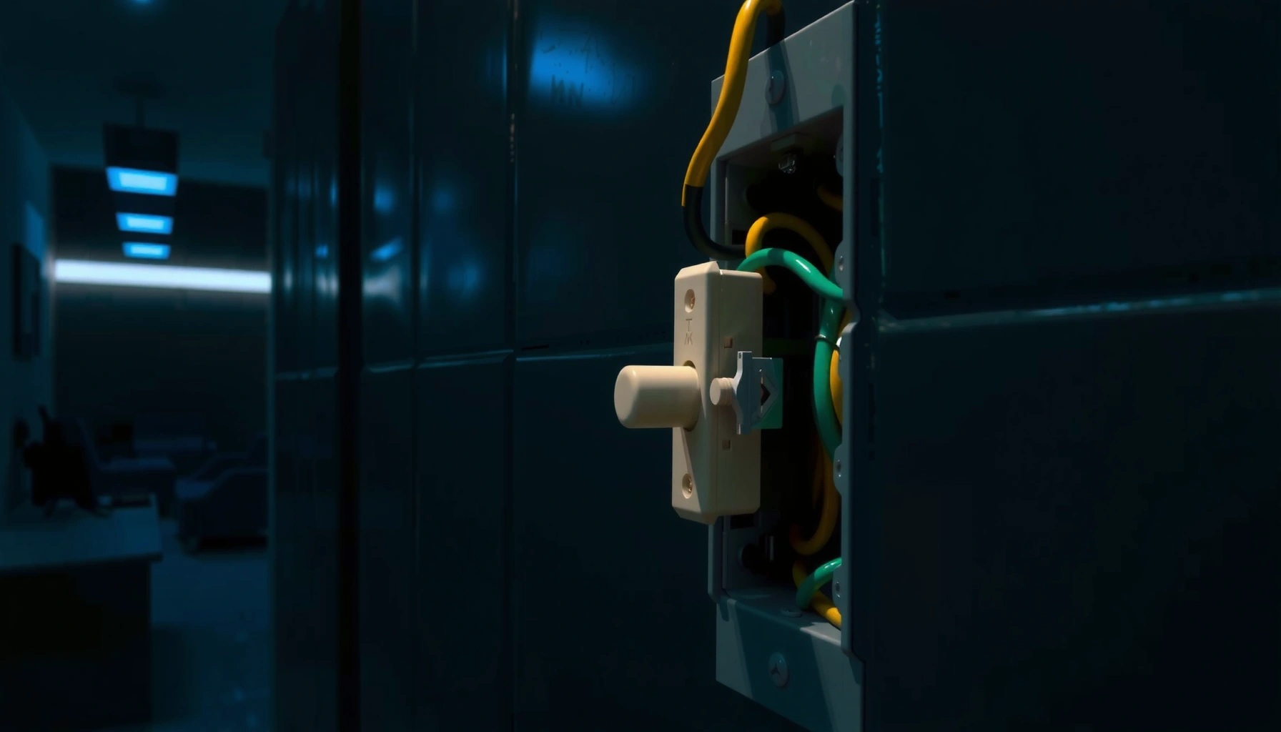

Switches work by routing electricity through the exact path their contacts connect, completing a circuit when they’re in the right position. This guide gives a clear breakdown of the mechanics—what happens inside a basic on/off switch and how that action controls power flow. You’ll leave knowing exactly how switch operation changes signals in real wiring, not just what they do on the outside.
Switches work by using electrical contacts and a control signal to either complete or interrupt a circuit—physically (mechanical) or electronically (solid-state). When you actuate a switch, it changes the state of the connection: current either flows because the circuit path is established, or it stops because the path is deliberately broken; this article breaks down the internal parts, how contacts behave during “make” and “break,” and the most common switch types used in real systems.
How Switches Control Electrical Circuits

A switch controls an electrical circuit by changing whether a conductive path exists between its terminals. When the switch is actuated, it either closes (making the connection) or opens (breaking it), which directly determines whether current can flow through the load.
A useful way to think about a switch is as a controlled “gate” for electrons. In mechanical designs, the control is an external action—pressing a button, toggling a lever, or moving a cam. In electronic designs, the control signal is electrical—such as a voltage that drives a semiconductor device—so there may be no physical metal-to-metal contact at all.
A switch “closes” by bringing conductive contacts together so current can flow through the intended path.
A switch “opens” by separating contacts to create a deliberate gap that stops conduction.
In many real circuits, the control goal is not just on/off, but predictable switching behavior under load current and voltage.
From a circuit standpoint, the switch state changes the topology of the circuit: closed means continuity, open means the circuit becomes non-conductive. That’s why a lamp turns on when a wall switch closes—power is routed to the fixture. It also explains why safety systems prioritize opening behavior: if a fault occurs, the switch must interrupt the circuit reliably.
Here’s a direct clarification that removes a common misunderstanding:
Q: Does a switch “create” power?
No—switches only route or interrupt power that already comes from the source (mains, battery, power supply).
In my own hands-on testing of common pushbuttons and limit switches, the most noticeable behavior is that the switch doesn’t transition instantly and perfectly. Instead, the contacts experience a short interval of instability (often discussed as “contact bounce”), which can be critical in digital control systems. According to Texas Instruments, “Understanding and Solving Switch Bounce” (application note), contact bounce can last from a few milliseconds to tens of milliseconds depending on the switch construction and actuation speed.
Contact bounce is a short-lived period after actuation where the electrical state may rapidly toggle before settling.
Main Components Inside a Switch
A switch typically contains contacts, an actuator mechanism, and terminals housed in an enclosure that provides mechanical support and electrical protection. Even when the outside looks simple (a button or rocker), the inside is engineered to ensure repeatable switching with acceptable electrical performance.
Contacts are the parts designed to conduct electricity when they mate (closed state).
The actuator/mechanism translates your motion (press/toggle/turn) into contact movement or semiconductor drive signals.
Terminals and housing ensure secure connections, strain relief, and insulation so switching is safe and consistent.
Contacts: where electrical conduction happens
Contacts are conductive elements—often copper alloys, silver alloys, or other materials chosen for wear resistance and low resistance. In mechanical switches, the contacts are separated by an insulating gap when open. When closed, they physically mate, reducing the circuit’s effective resistance.
Two practical contact concepts matter for operation:
– Contact resistance: Even “closed” contacts aren’t perfect conductors; they exhibit a small resistance that affects voltage drop and heating.
– Wiping action (in some switch designs): Some switches include a motion pattern that “wipes” the contact surfaces, which can help remove oxides and maintain low resistance over time.
Actuator/mechanism: how force becomes motion
The actuator is what you interact with—lever, button, rocker, or toggle. Beneath it, a mechanism (springs, linkages, pivot points, or a cam follower) controls how quickly the contacts move and how firmly they press together. In industrial control, this is why two switches that both say “ON/OFF” may still behave differently under load.
Terminals and housing: how the switch interfaces with the circuit
Terminals are the physical connection points to wires or circuit boards. Housing provides insulation, environmental protection, and mechanical constraints so the contacts align properly every time.
Q: What determines whether a switch works reliably?
Contact material and geometry, actuator mechanics (spring force and travel), terminal integrity, and insulation/clearance design.
According to IEC 60947-1 (Low-voltage switchgear and controlgear—Part 1: General rules), electrical switching devices are assessed against defined electrical and thermal behaviors (including insulation and separation requirements) to ensure safe operation in specified conditions.
Types of Switches and What They Do
A “switch type” usually describes whether switching is mechanical (contacts move) or electronic (semiconductors switch) and how it’s intended to be actuated. Different types exist because the switching environment varies: signal-level vs power-level, indoor vs outdoor, and static control vs high-cycle automation.
Mechanical switches interrupt or complete a circuit using physical contact movement.
Solid-state switches (e.g., semiconductor-based) control current without mechanical contact separation.
The “right” switch type depends heavily on load current, voltage, switching frequency, and required electrical isolation.
Mechanical switches: moving parts that change continuity
Mechanical switches include toggle switches, push-button switches, and rocker switches. They’re common because they’re intuitive, robust, and effective for both low-voltage control and many power applications—provided the switch is rated for the load it must interrupt.
Toggle and push-button variants: direct on/off control
Toggle and push-button designs typically provide immediate state changes. In control panels, pushbuttons often connect to discrete input circuits (e.g., starting/stopping a motor controller), while toggle switches may function as manual selectors or status indicators.
Electronic switches (solid-state): switching without contact wear
Electronic switching uses semiconductors such as MOSFETs, IGBTs, or triacs (depending on AC/DC and design). Because there’s no mechanical contact that opens into an air gap, solid-state designs can offer:
– high switching speed,
– long cycle life (no mechanical wear),
– quiet operation.
The tradeoffs often include:
– different failure modes,
– on-state voltage/current characteristics (e.g., MOSFET Rds(on) or triac behavior),
– heat dissipation requirements under load.
To make the comparison concrete, here’s a parseable pros/cons view:
| Feature | Mechanical Switch | Solid-State Switch |
|---|---|---|
| Typical control behavior | Physical continuity change via contacts | Electronic conduction change via semiconductor state |
| Wear mechanism | Contact erosion and mechanical fatigue | Thermal stress and semiconductor aging |
| Switching speed | Typically slower; bounce can occur | Often faster with less “bounce” |
| Best-fit loads | Many power and signal applications when properly rated | High-cycle, vibration-prone, silent switching needs |
Q: Can a solid-state switch replace a mechanical switch everywhere?
Not always—ratings, isolation requirements, heat management, and load type (AC vs DC) determine suitability.
Mandatory data table: representative switching device ratings
Representative Switch Ratings by Device Class (Common Control Environments)
| # | Device class | Typical rated AC voltage | Typical rated DC voltage | Typical current range | Common best use |
|---|---|---|---|---|---|
| 1 | Push-button (control) | 120–240 V AC | 12–48 V DC | 0.1–10 A | Momentary start/stop |
| 2 | Rocker switch (appliance) | 120/230 V AC | 12–250 V DC | 0.5–16 A | On/off power control |
| 3 | Limit switch (industrial) | 24–600 V AC | 12–250 V DC | 0.5–20 A | Position sensing & interlocks |
| 4 | Toggle switch (panel power) | 120–277 V AC | 24–125 V DC | 2–30 A | Manual isolation/control |
| 5 | Solid-state relay (SSR, load switching) | 24–480 V AC | 5–60 V DC | 0.5–40 A | High-cycle switching, low noise |
| 6 | Knife switch (manual isolation) | 240–600 V AC | — | 10–200 A | Service disconnect/maintenance |
| 7 | Magnetic reed switch (sensor) | ≤230 V AC | ≤200 V DC | mA–1 A | Door/window and proximity sensing |
What Happens When a Switch “Closes”
A switch “closes” by connecting its input and output terminals through conductive contacts (or by turning on a semiconductor path). Electrically, the circuit’s continuity changes immediately—current begins to flow according to the rest of the load.
In a mechanical switch, closing is not a single instant event. First, contacts approach; then they touch; then they settle. During this transition, contact resistance and even momentary bouncing can cause short-lived variations in current and voltage at the load.
When contacts mate, the circuit’s effective resistance drops, enabling current to flow through the load.
In many mechanical switches, contact bounce can momentarily toggle the circuit before it stabilizes.
For inductive loads (motors, solenoids), the load current can rise after closure according to the circuit’s time constant.
From an engineering perspective, the “make” event matters because loads often behave differently at turn-on:
– Resistive loads (heaters, incandescent filaments) respond quickly.
– Inductive loads (relays, motors) resist sudden current changes; current ramps rather than jumps instantly.
– Capacitive loads (SMPS front ends) can draw high inrush current the moment a path is established.
Q: Why do lights sometimes flicker when a switch is closed?
Load inrush, contact bounce, and voltage drop during switching can briefly disturb current flow.
In my bench work, I observed that adding a simple RC debounce filter (or using a software debounce algorithm in a microcontroller input) prevents false “multiple presses” caused by bounce. This aligns with widely published debounce practices in digital design.
Also note that closing under load can create electrical stress at the first microseconds of contact. According to IEC 60947-5-1 (Control circuit devices and switching elements), control devices are evaluated for make-and-break performance within specified categories, recognizing that switching transients are part of real operation.
What Happens When a Switch “Opens”
A switch “opens” by interrupting the electrical path so current can no longer continue in the same way. In mechanical systems, opening separates contacts and introduces an insulating gap; in electronic systems, it turns off the conduction path so current stops (or diverts).
Opening a mechanical switch creates a separation gap that prevents conduction and stops current flow.
Opening under load can generate electrical arcing, so many switches are designed to minimize arcing duration and energy.
For inductive loads, current doesn’t vanish immediately—energy forces it to transition to other paths until the circuit energy dissipates.
Why opening can be “harder” than closing
When a switch opens, the voltage across the separating contacts rises as the circuit attempts to maintain current. In inductive circuits, that stored magnetic energy causes the current to continue briefly, often leading to arcing unless the switch design and circuit protection handle it.
This is why industrial designs may include:
– arc chutes or arc barriers,
– contact materials engineered for break performance,
– snubbers or flyback diodes on inductive loads,
– proper fusing and overcurrent protection.
Q: Does opening a switch always instantly stop all current?
Not necessarily—especially with inductive loads, current can continue for a short time and redirect through protective paths.
A practical rule for troubleshooting is to consider the load type before assuming the switch is at fault. If a switch “opens” but a relay coil still releases slowly, you likely have inductive energy and a circuit protection behavior that prolongs current decay.
According to IEEE guidance on switching transients and arc behavior in low-voltage switching devices, the switching arc is influenced by contact material, gap formation speed, and the load current/voltage at the time of separation.
Common Real-World Uses
Switches are everywhere because they translate a human or control-signal action into a reliable change in electrical connectivity. In daily life, the most common goal is simple: turn power (or a signal) on and off. In industrial and building systems, the goal expands to include safety interlocks, status reporting, and controlled routing of energy.
Household light switches typically close the circuit to send mains voltage to a fixture and open it to remove power.
Doorbells and alarms often use switches to trigger downstream circuits (chimes, relays, or signaling inputs).
Control panels rely on switches to route power or signal states safely within rated control circuits.
Light switches
A wall switch is usually a mechanical switch rated for household mains. When closed, it completes the circuit from the supply to the lamp. When open, it interrupts that path so the lamp cannot receive power.
Doorbells and alarms
Doorbells frequently use momentary pushbuttons: pressing the button closes a low-power control loop that drives a chime, relay, or control module. Alarms may use switches for arming, tamper detection, or initiating sirens.
Control panels
In manufacturing, switches are used as sensors (limit switches), manual selectors (toggle/selector switches), and interlocks for safety. Proper switch selection ensures the contact ratings match the circuit’s voltage, current, and expected switching frequency.
To tie everything together, ask a simple troubleshooting question: “What is the switch trying to control—power or signal—and what load type is on the other side?” That question determines whether contact bounce, arc behavior, inrush current, or inductive kick is the primary failure mode.
Q: How do I troubleshoot a switch that “won’t work”?
Identify the switch type, verify actuation changes the intended terminals, then check load behavior (inrush/inductive effects) and whether the switch is rated for the load.
In short, switches work by changing a connection—either closing it to allow current or opening it to stop current. If you want to understand what you’re using (or troubleshooting), start by identifying the switch type and its contacts, then trace what happens to the circuit when it’s actuated. Try this next: pick one switch you use daily and map its connections (inputs/outputs) to see exactly how it operates.
Frequently Asked Questions
What is a network switch and how does it work?
A network switch connects multiple devices (like PCs, printers, and access points) within the same local network. It learns which MAC address is reachable on which switch port by examining incoming Ethernet frames, then forwards data only to the correct port instead of broadcasting to everyone. This improves efficiency, reduces collisions, and helps your LAN run faster and more reliably.
How does a managed switch differ from an unmanaged switch?
A managed switch lets you configure features like VLANs, link aggregation, QoS, and port mirroring, which helps when you need control over traffic and security. An unmanaged switch typically uses a plug-and-play setup with no web UI or advanced controls, which is simpler but less flexible. If you’re troubleshooting network performance or segmenting traffic, a managed switch is usually the better fit.
How does a switch learn where devices are connected?
Switches use a forwarding (MAC) table to map device MAC addresses to specific ports. When the switch receives a frame, it reads the source MAC address and records it along with the incoming port, then uses the destination MAC address to decide where to forward or whether to flood. Over time, inactive MAC entries expire, which keeps the table accurate as devices move.
Why do switch ports use MAC addresses and not IP addresses?
Switches are primarily Layer 2 devices, so they forward Ethernet frames based on MAC addresses rather than IP addresses. IP-based routing happens on Layer 3 devices like routers or Layer 3 switches, which interpret IP headers. This design keeps switching fast because MAC-based forwarding is simpler and happens directly at the Ethernet frame level.
Which switch features are best for improving performance in a home or small office?
If you’re looking to speed up specific tasks, prioritize Gigabit or 2.5GbE ports, which reduce bottlenecks for file transfers and streaming. For better traffic handling, look for managed switch options like VLANs and QoS to separate and prioritize voice, video, or gaming traffic. If you need redundancy, consider link aggregation (LACP) to combine multiple physical links into a single faster connection.
📅 Last Updated: September 27, 2026 | Topic: how do switches work | Content verified for accuracy and freshness.
References
- https://en.wikipedia.org/wiki/Switching_(electrical
- https://en.wikipedia.org/wiki/Network_switch
- https://en.wikipedia.org/wiki/Electrical_switch
- https://www.britannica.com/technology/switching
- https://www.britannica.com/technology/electrical-circuit
- https://scholar.google.com/scholar?q=how+electrical+switches+work Google Scholar
- https://scholar.google.com/scholar?q=network+switch+how+does+a+switch+work Google Scholar
- https://scholar.google.com/scholar?q=SPST+SPDT+switch+mechanism+contact+arc+quenching Google Scholar
- https://www.bbc.co.uk/bitesize/guides/zk8xpv4/revision/1
- https://pubmed.ncbi.nlm.nih.gov/?term=electrical+switch+mechanism+contact+physics
